Gizmo's new Firefly battery bank, working out the details
... written for Panbo by Ben Ellison and posted on May 6, 2016

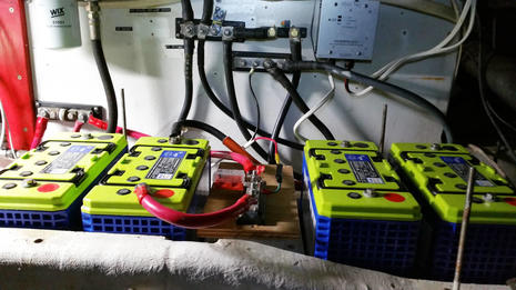
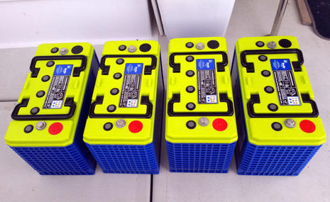
Gizmo_Firefly_Carbon_Foam_AGM_battery_bank_cPanbo.jpgWhen I wrote about replacing Gizmo's house battery bank, I was already inclined to try Firefly Oasis AGMs, and my enthusiasm has only grown. It certainly helped to have RC Collins and Nigel Calder testify further in that entry's comments about how deeply they've "abused" these batteries in ways that boaters like me tend to do. I'm excited about gaining significantly more usable, easy-to-replace power capacity, and the Firefly's smart, colorful exterior design is a nice bonus. But the switch from two conventional 8D AGMs to a four Firefly bank naturally led me to rethink Gizmo's battery storage, cabling, charging, and monitoring systems. The job isn't done yet, and maybe discussion of the details with you all will change the design again...

Firefly_Energy_battery_claims_aPanbo.jpg

First, though, let's review what makes Firefly a truly different lead acid deep-cycle battery. Presumptions about how hard you can use house batteries change radically when you can consume 80% of their capacity (about 1,000 times) and regularly charge them only partially without reducing their orginal capacity (though getting full capacity back does require a full charge/discharge cycle). The presentations available at Firefly Energy help to understand the technology behind the extraordinary claims (like above), and I also appreciate the assurances found in the Firefly Oasis user manual you can download at U.S. distributor Bruce Schwab Energy Systems.

I don't think that "...can be operated in a partial state of charge for long periods of time without sustaining any permanent damage" is what you're going to hear about other lead acid batteries if the manufacturer is being completely honest. And, by the way, Bruce Schwab strikes me as an honest salesman who knows his products well. He did not, for instance, mince words about quality control issues that some Fireflys suffered, though they seem to be over now. I'm sorry to add, however, that the $425 retail Firefly Oasis G31 price has gone up to $486 since I wrote the original entry and purchased my bank.

Kurt_Kelley_Firefly_Energy_former_CTO_aPanbo.jpgI also met Kurt Kelley, the guy who invented and perfected carbon foam battery plate technology starting in the Caterpillar's R&D department over fifteen years ago. To my great surprise he is now Firefly's Chief Technical Advisor, not Officer, and that change included moving to a nearby town in Maine! After a fascinating car ride with Kelley (and Calder), there's no doubt that Kurt's background in paleobotany played a part in developing the microcell plates that seem to revolutionize the way lead acid battery chemistry can function. But that's a story I hope to tell after getting some solid experience with Gizmo's Firefly bank and hopefully discussing it further with Kurt out on Penobscot Bay.

Spill containment, a recommendation

Gizmo_Firefly_battery_spill_containment__cPanbo.jpg

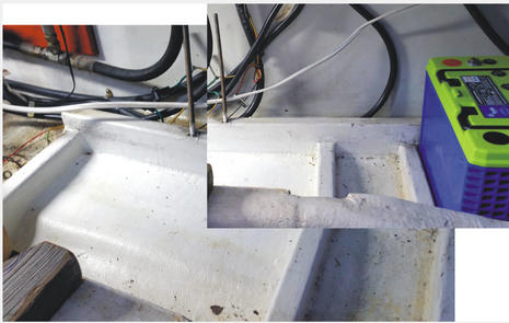
Now let's get to the nitty gritty of installing the four new Group 31 size batteries that would not quite fit into the boxes occupied by the old 8Ds. After helping two strong and limber young men get those 158 pound monsters forever out of Gizmo's engine room -- future owners, you can thank me now -- I was pleasantly surprised to find that Covey Island Boatworks had built a strong liquid-tight grid to hold the old battery boxes level and that the Fireflys neatly fit inside. I wasn't convinced that I had to provide battery spill containment because it's an ABYC recommendation, not a regulation; these AGMs contain a gel, not a liquid; and even spilled acid would not eat fuel, hydraulic or critical power cables unless this boat was also upside down for a while (unlikely). But, by golly, Gizmo got pretty good Firefly spill containment anyway.

I'll add that while I certainly pay attention to ABYC recommendations, I also feel free to ignore them if they don't seem to make sense for my particular application, unless an insurance company or another authority tells me otherwise. This is a subject that deserves more discussion, but for now I'll just add that I made epoxy-coated plywood pieces to level out the bottoms of two containment wells and also fashioned an elevated platform for that center section to hold a cable distribution block you'll see at the end.

Battery restraint, a regulation

CFR battery.jpg

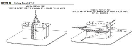
Battery restraint is a safety issue that's actually covered by the U.S. Code of Federal Regulations (CFR), and the USCG has done a nice job of explaining the regulations that pertain to marine systems like batteries with their Boatbuilder's Handbook. So Gizmo's new battery containment includes bottom cleats as needed to keep the Fireflys from moving fore and aft (and also to give them a little breathing room), plus there will be a top that is held down using the same four stainless studs and cross pieces that held down the old battery box tops. The end result won't quite be a box or boxes, but I don't think that's needed or required.

USCG_Boatbuilders_Handbook_page_aPanbo.jpg

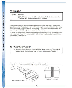
On the other hand, protection against accidentally grounding high current battery terminals is required and darn smart. Click the thumbnail image above to see the full Handbook page explaining the regulation and suggesting ways to comply. The Firefly bank will have non-conductive boots over all positive terminals and the top will cover the entire bank with a non-conductive surface. And I've been wearing safety glasses during the several hours I've spent messing around in close proximity to the batteries.

Balanced cabling, smart

SmartGauge_correct_battery_bank_cabling__aPanbo.jpg

I might well have muffed the battery cabling if it weren't for the sage advice of Alden Cole, who led me to the excellent SmartGauge analysis shown in part above. The two 8Ds that I'm replacing were cabled with both positive and negative load cables going to one battery and short jumpers to the second. It looked sensible and neat. But that's called Method 1 above and Chris Gibson (inventor of the amazing SmartGauge) makes a good case that it's a terrible way to install batteries, because unbalanced cable resistance means that the batteries will get used in an unbalanced way. The solution is positive and negative cable runs that add up to the same length (resistance) per battery, and it's not hard to achieve.

Blue_Sea_battery_cabling_gear__cPanbo.jpg

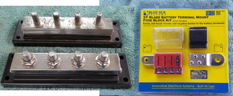
With further Cole counsel, I decided on Method 3, in which there will be positive and negative Blue Sea 600A PowerBars with same length cables going to each of the four batteries, and was glad I hadn't ever gotten around to putting the one I got to remove along with the generator on Panbo Classifieds. And when I purchased the new PowerBar at Hamilton's I also got a neat Blue Sea Terminal Mount Fuse Kit for the various small loads that must go direct to the battery bank. Incidentally, I was pleased to see a selection of Marinico BEP Pro Installer power gear competing with Blue Sea Systems at the store, but only a couple of Link Bars might make Gizmo's final install.

Below is the current temporary state of install. I'll use smaller gauge cable for the finished battery connections; they'll be easier to run so that all negative leads are on their proper side of the bar under the top that will actually hold down the batteries. Notice how much lower this bank is than the old boxed one, which really helps working in this area. On the other hand, Alden likes the idea of individual MRBF battery fuses in addition to the required 400A Class T bank fuse now mounted on the bulkhead, but they will raise the top. Your thoughts?

Also left to do are adjusting the bank's Balmar and Victron charging sources to the Firefly ideal of 14.4v absorption and 13.2v float -- the Blue Sky solar panel regulator is fixed but OK, I think, at 14.2v and 13.2v -- and working out a monitoring system worthy of this adventure in new technology (that's a new Victron shunt already in place). However, right now I'm a lucky guy about to check out America's Cup technology in New York and then fishing tech in south Florida, though I'd be quite happy to climb back into that cramped engine space en route to summer boat life with 12v power to spare.


Gizmo_Firefly_battery_bank_beta_setup_cPanbo.jpg

Comments

What an ugly installation, sorry.

Posted by: Anonymous at May 6, 2016 8:26 PM | Reply

Finally another one using a correct way to wire batteries. I have been using method 4 for many many years. When I show it to there boaters, their eyes glaze over and they must think "well he came from Amsterdam...so he must be....."

Method 4 keeps all the battery cable in the large battery boxes ( each with 4 batteries) I have and only 2 cables out

Then I use method 3 to combine all 3 boxes so 12 batteries correctly balanced.

Posted by: serenity at May 7, 2016 8:11 AM | Reply

Anon, beauty is in the eye of the beholder. As someone who does more of his fair share of installing and dealing with new technology this is a thing of beauty to me, especially given the fact it's not completed yet. On the first pass you do the best you can to get new tech in, working, and safely wired. This act alone usually comes with plenty of Whiskey Tango Foxtrot moments, and the need for clever creative MacGyvering along the way. Then you go back and improve it. Nice work Ben, and a great write up on this new battery tech.

Posted by: Bill Bishop at May 7, 2016 8:52 AM | Reply

Thanks Serenity and Bill! Maybe I wasn't clear how temporary that install is -- no cables have been cut yet -- or maybe Anon is having a bad day. Constructive criticism welcome, though.

Posted by: Ben E in reply to Bill Bishop at May 7, 2016 10:01 AM | Reply

Maybe Anon doesn't like the color scheme :-)

PS Blue Sea and Marinco are sister companies, so are they really competing?

Posted by: norse at May 7, 2016 12:55 PM | Reply

RC Collins of Compass Marine added an important comment to a Forum thread about monitoring individual battery temperatures:

https://www.panbo.com/forum/2016/04/wet-cell-battery-temperature.html

And, Norse, you're right, I forgot that Blue Sea and Marinco now have common corporate ownership. Let's hope that plays out well.

http://www.tradeonlytoday.com/2014/11/power-products-acquires-blue-sea-systems/

Posted by: Ben E at May 8, 2016 9:59 AM | Reply

I like MRBFs because they protect the wiring all the way to the battery (and make it easy to comply with ABYC's 7-inch rule). With multiple MRBFs, you can run cables of different gauges direct to the battery, while protecting each cable with a suitably-sized fuse. For example: a 4AWG to the alternator, a 2AWG to the house panel, and a 00AWG to the parallel switch.
Putting fuses between individual batteries in a bank is also possible, but seems like overkill to me. If this is what Alden has in mind, I'd be interested in the rationale for it.

Posted by: Jeff Zurkow at May 8, 2016 8:20 PM | Reply

I concur, and as a guy who is buying six L-16s in the next two weeks that'll comprise a big house bank for a passagemaker, this is timely.

I have no doubt your AGMs are fit for your purpose, and I love them for boats on moorings and start batteries due to their slow loss profiles and the fact you can lay them down. But in the long run, it's a proper and thoughtful and INFORMED installation that will make any battery or bank last longer and work safer. I particularly like that Blue Sea Terminal Mount Fuse Block Kit, because I have more than just a bilge pump I would like permanently wired and I dislike the usual rat's nest approach.

Posted by: Marc Dacey in reply to Bill Bishop at May 9, 2016 9:09 AM | Reply

The recommendations for the parallel wiring of multiple batteries were very interesting. People who have a really thorough understanding of a problem tend to uncover subtleties and details that are overlooked by others. Thanks for pointing to that information.

Posted by: Jim Hebert at May 9, 2016 4:28 PM | Reply

Ben, I didn't notice how much you reduced your total Ah capacity with the firefly batteries from your Ah capacity with the old batteries?

Being able to routinely discharge to 80% instead of 40% is a beautiful idea.

Posted by: Richard Gard at May 9, 2016 9:22 PM | Reply

The Blue Sea MRBF fuses are great products that can also be mounted to busbars but they are limited to 300A and would be a poor fit for any bank that could ever be used for starting an engine as large as Ben's.

MRBF to Busbar (background):
http://www.pbase.com/mainecruising/image/163140466.jpg

On sailboats with small AUX engines 300A is almost always perfectly adequate to handle all loads, but as we push into larger engines, and the need to accommodate the potential for thrusters, large inverters or large engine starting requires larger fuses & wire.

Best practice would be to size for any bank which can be paralleled in or switched to, in an emergency situation, or for any reason, and that bank should also carry over-current protection that can handle the starting loads without a nuisance trip.

Rather than loading up battery terminals or battery switches with spaghetti, I much prefer to use off-battery busbars for negative distribution as well as positive/switched & positive/always-on distribution. Blue Sea also makes a bunch of hubs that can be used for this.

What is lacking in the industry is a good high-amp fuse bus using ANL or Class T fuses where we can fuse for higher loads such as main battery bank protection, thrusters, inverters etc. and be able to bus them together.

I am often forced to create my own ANL or Class T distribution bus with copper bar stock (McMaster-Carr) and red adhesive lined heat shrink. Marinco now has some plated copper busbars for their new Pro-Installer line that can work OK for busing large fuses too.

As for fuses between batteries I have yet to see an internal short in a battery that could develop enough current between the good batteries and the bad one to trip a fuse that would not normally get tripped by the ships other high amp loads.

I currently have two internally failed AGM batteries in my shop, one orbital and one flat plate, both of them now 10V batteries as opposed to 12V. No matter what I do I have not been able to trip a fuse between a brand new AGM and the bad one even when one is at 100% SOC and the other battery has already failed internally. When the over-current protection is sized to not nuisance trip for the max load the vessel will develop it would seem a rare situation where fuses between batteries would trip when otherwise properly sized.

Posted by: Compass Marine at May 10, 2016 9:33 AM | Reply

Excellent points, Compass Marine. I confess I've been influenced by recent projects on auxiliary sailboats, where starting currents were modest and there was limited room to mount busbars. And thanks for the info on inter-battery fusing; I suspected it was unnecessary, but hadn't done any research.

Posted by: Anonymous at May 10, 2016 10:36 AM | Reply

Very timely info again here. I just purchased three G31 Firefly batteries to replace 5 LifeLine G27's on my sailboat.

I had also considered busbars to simplify some of the wiring at the battery side. I don't have 100% of it in place, as space is a constraint as Anonymous mentioned, but that's the route I would like to go as well.

I have used the Blue Sea MRBF fuses for a while on my boats, and love them - they were installed first thing on each battery.

I'm glad I don't have to deal with loads larger than 200A such as Ben's big engine starter - seems like there is a product gap there right now.

Posted by: Steve Mitchell at May 10, 2016 6:03 PM | Reply

The point of using fuses between batteries is primarily for safety in working around the batteries.

Modern AGMs have extremely high short circuit current ratings. For example, my G31 TPPL batteries have a short circuit current rating of 5000 amps. For the three batteries in the battery box, that's 15,000 amps if I ever do anything wrong while working on the system.

In balanced usage, I'm never actually passing more than about 50 amps per battery (charging or discharging), so I can put 50A terminal fuses on each battery and make the whole system much more inherently safe. Because it's fused at each battery, it also reduces the necessary maximum disconnect rating of the fuses (both the battery fuses and the main fuse).

Posted by: Tim Onders at May 10, 2016 10:51 PM | Reply

Ben what changes are you making to your charging systems to support the new Fireflys?

Do you already have heavy duty alternators? Tempurature sensors? Higher capacity charger? Larger power cables to your charging systems? Are Battery switch and fuse holders (not just fuses) rated for the higher potentials of these new batteries? Anything you have on a future to do list?

Posted by: Dan Corcoran (b393capt) at May 11, 2016 3:25 PM | Reply

Just a quick comment. ABYC E-11 does not require a fuse between the battery and the starter. The general reasoning being that over the long term a fuse in the starting circuit could fail due to fatigue and then the boater may be unable to start their engine in an emergency.
So far the industry really hasn't found out a good fuse solution for the starter.

Even though I would love for everyone to buy tons of MRBFs, I wouldn't install them if I was already installing class T fuses.

Andy Brown
Blue Sea Systems

Posted by: Andy Brown at May 11, 2016 7:53 PM | Reply

Ben,
Terrific discussion. Thanks for sharing it.
Love to see a schematic when you're finished.

I'm about to replace 3 4D gels on my BHM 28, and am following this with great interest, for the battery decision, as well as how I fuse and cable them up.

John

Posted by: John Hinckley at May 11, 2016 11:53 PM | Reply

Glad to see more updates on the Firefly batteries. Certainly an interesting new option.

However, specific to your installation, what's the story on installing blade fuses, such as in the Blue Sea 5024 block, directly on the positive bus of a battery bank capable of delivering 1000A+ short circuit. Isn't the ABYC spec that they need to be downstream of a properly AIC-rated fuse/breaker?

Posted by: Anonymous at May 12, 2016 12:56 AM | Reply

Ben,

Are you using the Firefly BEMS? http://fireflyenergy.com/wp-content/uploads/2015/05/BEMS_datasheet_Firefly-International-Energy.pdf

I don't quite understand it. Does it work on both charge and discharge? Is it an alternative to "balanced cabling". Is there an advantage to using both?

Carl


Posted by: Carl Nelson at May 15, 2016 11:53 AM | Reply

Hi Carl, I don't entirely understand the BEMS either, but note that "It is designed to equalize old and new batteries connected in a series string..."

So the BEMS is not useful for an all parallel 12v bank like mine, but might be useful for a 24v boat bank that is partially serial and partially parallel. (Actually, according to the spec sheet it can be used with 2, 4, 6, and 12v batteries in series strings totaling 24 to 48 volts.)

Posted by: Ben E at May 15, 2016 12:05 PM | Reply

I checked the interrupt capacity specs of some Blue Sea blade fuses for the 5024 you mention -- they were all 1000 Amps. Does that reassure you?

Posted by: norse in reply to Anonymous at May 15, 2016 11:00 PM | Reply

I'm just a tad worried about the fuel filter and lines above the batteries. I'd move that too.

Posted by: Anonymous at May 16, 2016 8:29 AM | Reply

The hoses and filter are actually part of the hydraulic steering system, plus neither of the well accredited surveyors who've checked out Gizmo while I've been present had any problem with the house batteries in that same location.

Posted by: Ben E in reply to Anonymous at May 16, 2016 2:35 PM | Reply

I saw your note about using a solar charge controller that isn't really multi stage nor adjustable. I installed a Midnite Solar KID solar controller on my boat about 12 months ago and couldn't be more happy with it. I drive it with 2 flexible 135w panels in series (theoretical 270w total with peak voltage about 60v into the MPPT controller). It has adjustable bulk, absorption and float voltages and a ton of other features. Seems very well built and efficient.

Posted by: Robert at May 16, 2016 5:55 PM | Reply

Thanks, Robert; the Midnite Solar controllers look interesting:

http://www.midnitesolar.com/products.php?menuItem=products&productCat_ID=43&productCatName=Charge%20Controllers%20-%20KID

But my Blue Sky 2521i was about half the cost, has held up well, and does have bulk, absorption and float charging stages. They are not adjustable but pretty close to Firefly ideal, as noted above. Here's detail on my 2012 solar install:

https://www.panbo.com/archives/2012/08/greening_gizmo_17_amps_of_solar_panel.html


http://www.blueskyenergyinc.com/products/details/solar_boost_2512i/

If I make a change, it will likely be the Victron BlueSolar MPPT 100/30. It's multi stage and voltage adjustable, and I think it can also integrate with the Victron BMV and a Color Control GX for some pretty specatular off boat power monitoring and also conversion to NMEA 2000. I'm researching the possibilities.

https://www.victronenergy.com/solar-charge-controllers


Posted by: Ben E in reply to Robert at May 17, 2016 8:33 AM | Reply

Ben,

Your BS 2512i is programmable but you would need the Blue Sky IPN-Pro Remote or the Blue Sky UCM module in order to do that. Currently you have the basic IPN Remote. The IPN-Pro or the UCM will give you full programing of the absorption & float voltage settings as well as many other features such as absorption time.

That said the Victron controllers with the optional VE Direct BlueTooth dongle allow you to track the controller on your phone, program it from your phone and they cost less (when buying new) than the equivalent controller plus IPN-Pro from Blue Sky..

A Victron 100/30 plus the BT Dongle will run you about $270.00 for both. The IPN-Pro Remote alone will run you about $200.00 to add to your existing controller or the Blue Sky UCM would run you about $270.00.

The Midnite KID is a great little controller but I feel they missed the mark on some fronts. The awkward size, mounting options, and no remote option being a few of them. While it is a great controller for boats it can often be a bulky & awkward installation.

The new Morningstar ProStar 25 controller is also quite nice but again more costly than the Victron.

Posted by: Compass Marine at May 17, 2016 9:56 AM | Reply

Ben, the Blue Seas MRBF's are a great solution for a lot of applications,with one significant drawback - they add almost two inches of total height to the existing post. The stud itself is 1.75" long, and then the rubber insulator cap goes over that.
When fitting these to existing boats equipped with battery boxes, it almost guarantees you won't be able to get the lids back on the box!
I've run into this before, and suggested to Scott McEniry over at Blue Seas that they consider designing the fuse holder with an offset, so the total height is still comparable to the original post - that was in 2014, so I guess my idea didn't get far.
I see the Firefly's have a bolt terminal as opposed to a post, so you not have an issue in Gizmo...

Posted by: Grant at May 17, 2016 1:22 PM | Reply

"... MAY not have an issue on Gizmo."

Posted by: Grant at May 17, 2016 1:24 PM | Reply

Grant,

If you have lead post battery terminals the solution in the pic below works with MRBF's. For Lifeline, Odyssey, Northstar Firefly etc. you can make a right angle 90 out of copper bar stock but I find a short jumper to an ANL or Class T or short jumper to a busbar mounted MRBF works too.


Horizontal MRBF:
http://www.pbase.com/mainecruising/image/160258247.jpg

Posted by: Compass Marine in reply to Grant at May 17, 2016 2:21 PM | Reply

Thanks guys - but by the looks of that picture, you're still not going to be able to keep it all inside the box. The only difference is now it hangs out the side, instead of poking through the lid!
I'm all for creative solutions, and I appreciate your tip - but I think the best solution is just to re-design the profile of the holder in a "Z" type shape, and perhaps reduce the length of the stud as well (which seems overly long). I love about 99% of Blue Seas products, but I think there's room for improvement here...

Posted by: Grant in reply to Compass Marine at May 17, 2016 6:46 PM | Reply

Thanks from me too, but I'm not planning to use MRBF fuses on each battery. I think the accidental short risk when working without a cover is manageable, and the exceptionally flat top design of the Fireflys allows for a snug protective cap.

But here's a question: these pre-made Ancor 18-inch 2 AWG gauge cables look like they'll do the job linking each battery to the Powerbar terminal blocks...

http://www.defender.com/product3.jsp?path=-1|328|2290011|2289961&id=193184

...but what do you all think?

Posted by: Ben E at May 17, 2016 8:19 PM | Reply

Ben, do you use a charger for shore power to 12V charging, and if so which type? (Is it the Balmer or Victron your refer to in your post?) I recently also bought 2 Fireflies that will use a programmable Victron 75/10 solar charge controller (and Bluetooth dongle to allow monitoring from a smartphone) for charging at sea/anchor, but have found it hard to find any chargers for shore power that will float at 13.2V - most seem to float at 13.4 or 13.5V instead, and that is not recommended per the Firefly specs (will reduce battery lifetime). It seems harder to find a suitable programmable shore charger than a good programmable solar charge controller.

Thanks for sharing your experience redoing your battery bank - lots of very useful discussion here and in the earlier posts!

Posted by: Stephane at May 18, 2016 1:04 AM | Reply

Hi Stephane,

I installed a Victron MultiPlus 12/2000 in 2012, details here:

https://www.panbo.com/archives/2012/05/victron_multi_in_onan_genset_outa_greener_gizmo.html

At the bottom of that entry is a "VE Configure II" screenshot showing how you can totally customize the charging voltages and much more.

So, yes, I can set the Multi to float at 13.2v, but I'll need to borrow a special Victron USB dongle (Victron data protocols are really confusing). The Bluetooth dongle seems great, especially for professionals who work on many boats.

Posted by: Ben E in reply to Stephane at May 18, 2016 7:44 AM | Reply

Stephane,

The Sterling ProCharge Ultra charger has a custom profile setting that can be used to set 14.4V & 13.2V. They largest model is 60A.

Posted by: Compass Marine in reply to Stephane at May 18, 2016 9:41 AM | Reply

Ben, the Ancor pre-made cables you referenced are great from a quality and value standpoint, if they meet the AWG you need for your loads and happen to be the correct length. I prefer to make up my own cables, because I can cut them exactly the correct length, which I believe was part of the discussion in terms of equalizing voltage drop among the batteries. Also, on short lengths, you can crimp the lugs on the correct "clock" orientation for the terminals they are attached to, which avoids twisting the cable to make things line up. But this requires some rather expensive tools which you may not want to acquire for infrequent jobs...

Posted by: Grant in reply to Ben E at May 18, 2016 11:02 AM | Reply

Ben,

Email me your lengths and lug sizes and I can make your battery cables to the exact dimensions you need. Measure twice cut once.. (wink)

Posted by: Compass Marine in reply to Ben E at May 18, 2016 11:07 AM | Reply

Completely agree with RC and Grant. I make my own cables for the same reasons cited above - exact length and loss, and orientation of the lugs. I'm also slightly OCD so having cables that aren't the exact length drives me insane.

Posted by: Steve Mitchell in reply to Ben E at May 18, 2016 12:06 PM | Reply

Thanks, RC, Grant & Steve, but actually 18 inches is a perfect length for all eight Method 3 (star pattern) battery connects in this lucky case. With the PowerBars on center of the bank and at similar distance to their respective poles, equal length cables make sense (and are easy to figure out -- 18 is the longest run to the four target poles from either PowerBar ;-).

At $23 a piece for what look like quality factory-made Ancor cables with right size lugs, it seems hard to justify custom cables (tho thanks for the offer, RC!).

However, I may use red cables on both sides because Ancor's black pre-made cables have 5/16 lugs. That will probably cause consternation from the "peanut gallery" here, but, heck, the Covey Island Boatworks folks who originally wrestled so much 4/0 cabling into Gizmo -- it wasn't needed, but it works great -- fairly often used wrong color cable but simply marked it correctly with tape or shrink tubing.

But I'm still in "listening to advice" mode and not too hurried (it's going to be a late launch for other reasons).

So far no one here has objected to 2 AWG cables for those individual battery connects, but it's not too late ;-) I've been advised that it's plenty big enough and see in the Ancor tables that 15 feet of 2 AWG -- ten times my lengths -- can carry 100 amps with a maximum 3% voltage drop (i.e. heat creation).

But then again I don't fully understand what "Instantaneous P: CA/CCA ..... 800/600" means on the Firefly Oasis G31 spec sheet. Anyone?

Also while looking for amperage specs I noticed again in the Firefly manual that not only is 13.2v float strongly recommened but "The Oasis does not require a float charge." They are different!

Posted by: Ben E at May 18, 2016 12:32 PM | Reply

Ben,

2 AWG cables should be fine for battery interconnects.

CA = Cranking Amps
CCA = Cold Cranking Amps

From www.gnbsystems.com/faq (and many other sources):

"Cranking amps are the numbers of amperes a lead-acid battery at 32 degrees F (0 degrees C) can deliver for 30 seconds and maintain at least 1.2 volts per cell (7.2 volts for a 12 volt battery).

Since it is more difficult for a battery to deliver power when it is cold, and since the engine requires more power to turn over when it is cold, the Cold Cranking rating is defined as: The number of amperes a lead-acid battery at 0 degrees F (-17.8 degrees C) can deliver for 30 seconds and maintain at least 1.2 volts per cell (7.2 volts for a 12-volt battery)."

I never did find the G31 Spec sheet you referred to online, but as you're dealing with a house bank as opposed to a start bank, you really don't care about cranking amps anyhow. Your research to this point on Amp-hour capacity, depth of discharge, etc. is far more relevant to what your usage will be. Hope that helps -

Posted by: Grant in reply to Ben E at May 19, 2016 12:20 AM | Reply

Sorry, Grant, I didn't express myself well. The Firefly spec handout (and the manual) are at the bottom of this page:

http://www.bruceschwab.com/advanced-energy-storage-systems/firefly-energys-oasis-group-31/

The spec table is a little odd and I wasn't sure it meant 800 CA and 600 CCA, but I guess that's right. And I guess those values are OK with the 2 AWG cables, which was my thought. Thanks!

Posted by: Ben E in reply to Grant at May 19, 2016 6:38 AM | Reply

As a head's up to readers, I contacted Firefly to purchase batteries, and found out that only Hybrid Power Supply -- http://hybridpowersupply.com/firefly-energy/ -- is authorized to distribute Firefly in Canada. Some websites claim otherwise, but they are off-base for doing so. Not sure if there is any legal implications, but people need to respect business boundaries and it appears some people aren't doing that.

Posted by: Anonymous at May 19, 2016 9:01 AM | Reply

Thanks for the link, Ben - I see the table now, and it IS confusing! And I'm as baffled as you regarding the meaning of "Instantaneous P". That's a new one on me.
By the way - a couple of other options for your negative cables would be to buy the black pre-made cables and carefully drill out the 5/16" terminals to 3/8" - or just re-terminate them with the proper lugs (yes, you would lose an inch of length in that case).
But really - I think Gizmo deserves some proper custom-made cables if you're going to all this trouble anyhow - and besides, the DC negative really ought to be yellow, not black!

Posted by: Grant in reply to Ben E at May 19, 2016 11:48 AM | Reply

Yeah, yeah, but I'm a skinflint Yankee and how could Ancor made cables not be "proper"?

Thanks to the Hybrid Power link just above your comment, I found another Firefly spec sheet that doesn't list CA or CCA at all, just 500A max discharge at 77F:

http://hybridpowersupply.com/wp-content/uploads/2015/03/Oasis-G31-FF12D1-RE-Spec_hybrid.pdf

Posted by: Ben E in reply to Grant at May 19, 2016 2:10 PM | Reply

I'm sure they're proper - except for the wrong size lugs! If you're OK with black - maybe check out these as well:

http://www.bestboatwire.com/custom-cables

A custom-made 1.5' 2AWG cable with heavy-duty lugs and heatshrink came out to $ 11.84 - pretty reasonable, I thought...

Posted by: Grant in reply to Ben E at May 19, 2016 2:28 PM | Reply

note from the peanut gallery-- yellow negative cables would go well with the color scheme and color code, and it's easy to do with shrink-wrap.

AWG 2 corresponds to at least 100 Amps in that table, per battery, so 400 Amps combined. How big is your max load?

But note that the length given is positive and negative combined, so it's not really 10 times your length. Still good though.

Posted by: norse in reply to Ben E at May 20, 2016 2:45 AM | Reply

Doing yellow cables with shrink tubing is fine, but getting yellow (or red or anything but black) means you aren't getting the best possible insulation material. If you are using Welding cable for flexibility, black Hypalon is the ONLY choice of jacket you want.(Just ask RC!)

Posted by: Hartley at May 20, 2016 9:00 AM | Reply

Actually I meant yellow over red, but that is good to know. I've learned a lot from this thread.

There's an interesting article in the current issue of Wooden Boat about using Firefly batteries to replace the engine in a sailboat:

WoodenBoat 250, May/June 2016
Electric Auxiliary for a Sailboat — With solar recharge, off-the-grid cruising is in range by Jonathan Taggart

Posted by: norse in reply to Hartley at May 20, 2016 12:17 PM | Reply

A lot of boaters over here have a start-, service- and bow thruster battery in their boat. A state of the art FET charge current distributor keeps them apart while charging and discharging. Am I wrong to say that an intelligent x-phase charger is useless in this set-up because the charger can't 'see' (measure the voltage of) the batteries he is charging, so a constant voltage charger would be the only option when using a FET distributor and multiple batteries ?

Posted by: Leo Starrenburg at May 20, 2016 12:50 PM | Reply

Leo, I think it would work fine. The FET charge distrubutor will be "on" when charging, so the charger will "see" the batteries downstream of it. The FET distributors work the same as the older relay versions, but faster and quieter without the drain and potential for mechanical failure.
They only isolate the batteries when discharging.

Posted by: Hartley at May 20, 2016 1:28 PM | Reply

I will be adding solar and rewiring my battery banks this summer so I've been following along, learning and gathering ideas. I thought I had my plan figured out using Blue Sea ACR's to control charging of start and thruster batteries. Then came FET charge distributor??? Can someone point me to information about FET systems. Thanks.

Posted by: Arch at May 23, 2016 7:08 PM | Reply

Arch, try this link:

https://www.victronenergy.com/upload/documents/Datasheet-Argo-Fet-Battery-Isolators-with-alternator-energize-input-EN.pdf

I got the FET 3 output 100 A and it works great.

w fr greetings, Leo

Posted by: Anonymous at May 24, 2016 2:47 PM | Reply

Keep in mind that when using traditional diode or FET based isolators most charge controllers, smart battery chargers and wind controllers today are looking for voltage on B+ wire in order to work/turn on. This is a safety feature designed to prevent charging into a dead or internally shorted battery. Because isolators block the controller or charger from sebsing voltage on the input stud, before turning on, they make for a rather poor fit when using alternative energy or smart chargers to feed multiple banks.

Some isolators feature a "key-on" excite terminal but this would require the isolator to always be powered, if you used other charge sources, such as solar for charging multiple banks.

Combining relays or voltage sensitive relays (VSR's)such as the Blue Sea ACR or the Yandina Combiner etc. do not suffer these issues. These devices are extremely reliable, so reliable that Yandina actually puts a lifetime unconditional guarantee on them. I have never seen a Blue Sea or Yandina Combiner fail.

Another alternative for charge management would be to use a battery to battery charger such as an Echo Charger, Duo Charger or the Sterling Battery to Battery chargers.

Posted by: Compass Marine at May 26, 2016 3:04 PM | Reply

I used a VSR in the past, it looked at the voltage of the starter battery and when that was high enoguh it changed over to the house battery. Now that I have three batteries I use a FET isolator. This does just what the name says: it isolates the batteries; no more, no less. When I connect a constant voltage charger to the input, all 3 outputs will deliver current to all the batteries, the amount of which varies with their respective levels of discharge. And yes, my FET isolator has an 'energize' input to connect to the + of a battery in order to get 12V on the B+ output of my Bosch altenator. It draws just 10mA but the altenator needs to see the 12V in order to work. So I hooked up a wire from the engine 'contact' key-switch to the energize input of the FET isolator.

Posted by: Anonymous at May 26, 2016 3:20 PM | Reply

I'm with RC on this one - the voltage-sensitive combining relay is reliable and doesn't require a work-around to start the alternator. I have two on ATSA - a bit Blue Sky between the house #1 and #2 and a small West Marine one between the House #1 and the Start battery.

The FET device has an advantage over the older diode technology because it doesn't have the .5 to.6 volt drop across it, with a 20-30 millivolt drop instead - a bit deal when you are trying to keep your batteries properly charged.

What I don't understand is why the two technologies couldn't be combined - use an FET switch (instead of an electro-mechanical relay)in a voltage-sensitive combiner? The low voltage drop means you could connect your house primary battery direct to the alternator (eliminating the kludge of "ignition bypassing") and having the combiner add in the other batteries when the voltage on the primary gets high enough.
Alternatively, just use the "FET distributor" between your primary battery and the secondary ones, and connect the alternator, AC charger, solar, etc. to the primary directly.

Posted by: Hartley at May 26, 2016 3:39 PM | Reply

QUOTE: "Alternatively, just use the "FET distributor" between your primary battery and the secondary ones, and connect the alternator, AC charger, solar, etc. to the primary directly."

Because it would not isolate the house battery. Any load applied to the start, thruster etc. bank would place a load on the house bank.

Wired properly (many are not) VSR's work tremendously well, are incredibly reliable and don't really have any voltage drop to speak of..

Posted by: Compass Marine at May 26, 2016 6:16 PM | Reply

Hi RC,

I see what you mean - for the start or thruster battery I don't see the harm, but with two house batteries, that would be bad.
I still think my original idea of using the FETs in place of the electromagnetic relay in a VSR would be useful, though. :)

Posted by: Hartley at May 26, 2016 7:26 PM | Reply

I am wondering if anyone has been able to get the Balmar Smartgauge to work properly with the Firefly batteries? So far I have had no luck using program #5 Carbon Fiber Lead Acid (initially recommended by Balmar) or program #1 Deep Cycle wet cell recommended by Mr. Compass Marine himself. Both end up giving a way overly optimistic percentage for remaining battery life.

Luckily I already had an amp hour counter type of meter, but I was hoping this would be a good addition to give a more true battery life percentage as the ah counter inevitably gets out of whack.

Balmar admitted to me in an email that this was designed before Carbon Foam AGM's were around. They have plans to include a specific program for Firefly batteries in the next version - which is at least a year and a half away. At this point it is looking like I purchased a fairly expensive useless meter.

Posted by: Greg Davids at June 14, 2016 7:58 PM | Reply

Greg,

I have a Firefly setup with the Balmar meter as well. I have been doing a ton of testing the last 2 months in preparation for a couple of long trips where I will need the extra capacity.

I have also seen some very odd results from the Balmar meter. I don't remember what I have it set to battery-type-wise, but I have seen it get "stuck" at 91% for a long while even though the bank is completely charged. After killing the charger for a couple of hours and letting it re-charge again, the Balmar meter catches back up.

I also have seen it give me a far more optimistic reading than I expected. How are you calculating it outside of the Balmar? Purely based on voltage levels?

Anyone know other meters that could give more accurate readings?

Posted by: Steve Mitchell in reply to Greg Davids at June 14, 2016 8:24 PM | Reply

Steve,

I have a preexisting Xantrex Link 20 battery monitor which counts amp hours. I have 4 of the Firefly batteries on the house bank - should be 440 amp hour capability. I have allowed the batteries to drain to drain a bit over 50% a few times now based on counting amp hours and the Smartgauge is showing itself to be not so smart. I have not seen it show lower than the low 70% range. As you mention, it does seem to like staying in the 90% range even when clearly much more capability has been used.

I have not logged the specific numbers as scientifically as I should, but the basic fact is it reads much higher in percentage than the actual value could possibly be. This is at least the case for program 1 & 5.

Posted by: Greg Davids at June 15, 2016 12:21 AM | Reply

This is all good information but we must keep in mind that there are a lot of variables at play such as charge devices moving to float prematurely, Peukert etc.

In testing I have been able to get the SmartGauge to track pretty accurately to the Firefly but the bulk of my testing was done before the Firefly hit my bench. I do know that Carbon fiber is not the setting to use.

I have been using either #1, #2 or #3. It is possible that #1 has too high a full charge voltage expectation (14.6V) outside of a lab like environment where absorption can be held as long as it takes. I have been trying to get an optimal setting list, for batteries listed by brand & type, out of Balmar now for approx one year. Apparently the guys at Merlin have not responded and I know the owner of Balmar has been pushing the issue. I actually sent Tim a list with the batteries I wanted the optimal setting types for, seems easy, apparently not....

With the SmartGauge you do however need numerous deep cycles and recharge events for it to "learn" the bank. You should ideally not pay much attention to it during charging and should wait until you are discharging again and it again finds its place. The longer it remains connected the faster it seems to narrow in on SOC upon discharge.

If you have changed settings for battery type you will ideally want to do a full factory reset and start the deep cycles over again. The longer it remains connected the more accurate it becomes. I can tell you that my own Firefly has remained uncharged now for over 8 weeks and the resting OCV, as of yesterday, was 12.96V. A full Firefly will rest at over 13.0V yet with many of the charging systems installed on boats getting to 100% SOC may be a much rarer event than most assume. Hanging at 91% SOC for example could be because the charge source dropped to float far too early, not at all uncommon. At a premature 13.2V float the charge rate will be a snails pace.

Ah's out do not always equal SOC unless they were drawn out at the 20 hour rate at 77F. If you are discharging at say 25% of the 20 hour rate (5.5A vs. 22A) the battery bank will actually have slightly more capacity than 440Ah. Most Ah counters DO NOT calculate for any overages in Peukert only high discharge impacts on the negative side but the SmartGauge can more accurately account for this.

The best correlation is to let the battery sit for 24 hours at a temp between 70F and 80F and look at resting open circuit voltage and compare it to the SmartGauge's SOC.

If you want to see a real world example of how well the SmartGauge can track (though these are not Firefly however) this one is interesting (Smart Gauge part at end):

How to Murder Batteries in Half a Year

http://forums.sailboatowners.com/index.php?threads/how-to-murder-batteries-in-half-a-year.175669/

I would be curious to see how it tracks on setting 2 & 3 compared to #1. Unfortunately the Firefly I have been using for testing is in the middle of more testing and can't be used for SG testing right now...

-RC

Posted by: Compass Marine at June 15, 2016 9:12 AM | Reply

I have now changed over to the program #3 AGM setting. I will report back after it has gone through a couple cycles. Unfortunately, since I live on the boat, doing a 24 hour open circuit test just isn't gonna happen.

I am using a Victron battery charger with a separate voltage sensing lead attached to the batteries. I would think this would help with avoiding a premature float. My sense is that this is not happening. I did program the Link 20 with the Firefly recommended Peukert value - though it is interesting you say this is only factored in for extra high loads and not smaller loads. We definitely spend most of our time with loads less than 22amps.

Posted by: Greg Davids at June 15, 2016 9:55 AM | Reply

Greg,

For a little more depth on Ah counters:

Keeping Your Ah Counter More Accurate:

http://www.pbase.com/mainecruising/programming_a_battery_monitor

-RC

Posted by: Compass Marine in reply to Greg Davids at June 15, 2016 10:54 AM | Reply

After just one day I can tell that program #3 is much more accurate for the Firefly batteries. My amp hour meter tells me that I have consumed 120.7 amp hours. This should theoretically leave me with 73% remaining battery life. The Smartgauge is now reporting.... drumroll.... 74! Pretty darn close.

Given that this is just the first cycle, and it is supposed to get more accurate over time, I would say this is a winner.

Posted by: Greg Davids at June 16, 2016 12:00 PM | Reply

Greg,

I was actually using battery program #1 and had very good results. I switched to #3 as you are using, and I am getting weird results when the batteries are fully charged and in float.

The Balmar is showing 82-89% full even when the batteries are fully charged and in float.

If I kick off the charger, and let the batteries drain down a bit, things get better, but not much.

I think I may go back to program #1 - have a week long trip starting this Friday and want this to be as accurate as possible.

Posted by: Steve Mitchell in reply to Greg Davids at June 22, 2016 4:52 PM | Reply

My further experience with program #3 is not quite as good as the first cycle I reported on, bit it's still definitely better than Program #1 or #5.

Currently with the battery fully charged and in float mode at 13.2 volts, it is showing 99%. Fairly quickly after removing shore power it does drop down to the low 90's. By the time it is in the 80 % range it is starting to be reasonably accurate. When it was closer to 75% I would say it was reading only about 3 or 4% lower than it should - according to my amp hour meter. That is close enough for me.

The other programs were reading much higher than was possible. I guess I would rather have it give me a slightly pessimistic figure than a wildly optimistic figure. Of course it would be best to simply be accurate.

It sure would be nice if we could load an updated firmware that included a proper program for these batteries. I am guessing that based upon all the recent positive press (and the manufacturer feeling they can get away with a decent price jump), sales of these batteries must be doing well.

Posted by: Greg Davids at June 23, 2016 12:23 AM | Reply

I'm thinking about buying a PanelPilot and configuring it to a 24h graph to show the trend of the service batteries' voltage. It's not as sophisticated as an intelligent capacity monitor, but you'll see what's going on at a glance.

http://www.panelpilot.com/panelpilotm

http://www.starrenburg.eu/pp1.JPG

cheers, Leo

http://www.starrenburg.eu

Posted by: Leo Starrenburg at June 23, 2016 4:54 AM | Reply

The PanelPilot has arrived, as has a Hall-effect split core current sensor. Next week I'll make a test setup, the display has two voltage inputs, I'll use one for the battery voltage and the other for the current sensor, my version gives 0 to 4Vdc out for 0 to 100 Amps. I have to see which is most practical, a voltage only display with the 48h graph, or a voltage and current display for the charging current. The nice feature of the PanelPilot is the easy configuring of a lot of display types and voltage (conversion) ranges. Will be back with the results of the test.

Posted by: Leo Starrenburg at June 27, 2016 5:08 PM | Reply

Ben - can you post the custom settings for the Balmar MC-614 for your Firefly batteries?

Posted by: Gary Warner at September 18, 2016 6:53 PM | Reply

Sorry, Gary, I'm headed to NMEA conference and the Balmer notes are on the boat. But I do know that the major change Rod Collins recommended for my Firefly setup was setting the adsorption time period to 4 hours.

Actually it would be great if Rod chimed in as he understands the issues MUCH better than I. Otherwise it will have wait until next week.

Posted by: Ben E in reply to Gary Warner at September 19, 2016 9:36 AM | Reply

After a long road of install, configuration, reconfiguration, yelling, and testing, I've finally written up part 1 of my MasterVolt+Firefly setup on Grace at https://www.sailbits.com/blog/2016/09/power-system-design/

More to come in terms of the actual installation, configuration and of course actual use over the last few months.

Posted by: Steve Mitchell at September 20, 2016 5:50 PM | Reply

I followed this thread with interest and am considering Firefly batteries for my next upgrade. It would be great to hear what your experience has been now that you've had them onboard for a while

Posted by: James Douglas Gregory at December 16, 2016 9:44 AM | Reply

James,

I've had mine since Feb 2016 and absolutely love them. I've been on a number of trips this last summer away from the dock and have had great results with how far down they discharge and how quickly they charge in general.

I am 100% satisfied and I haven't said that about batteries in a long time.

http://www.sailbits.com/blog/2016/09/power-system-design/

Posted by: Steve Mitchell at December 16, 2016 1:10 PM | Reply

I just replaced my house bank with Fireflys and am planning on installing a SmartGauge. I'm wondering if there has been any update to how best to configure the SmartGuage for this battery type? Also, is the SmartGuage firmware user updateable so that it can be reconfigured as technology changes? Thanks for any information.

Posted by: Chuck Lanter at February 6, 2017 8:35 PM | Reply

Hi Chuck,

Last July I wrote a bit about how a SmartGauge is not working well with my Firefly bank...

https://www.panbo.com/archives/2016/07/summer_fun_camden_panbots_gizmo.html

...and the situation is about the same though I did try a different battery profile in the SmartGauge. The Victron BMV600S is doing better at tracking State of Charge, but it's not perfect either.

In both cases, there may be more I can do to adjust the gauge to the batteries, and researching that is getting to the top of my winter to-do list.

PS I don't think the Smartgauge can get a firmware update in the field.

Posted by: Ben E in reply to Chuck Lanter at February 7, 2017 7:57 AM | Reply

I also find my Smartgauge does not work well with the Firefly batteries. In retrospect that was a bad purchase - the monitor, not the batteries. I think you are better off with a monitor that counts amps in and out. The manufacturer of the Smartgauge said they are working on a newer version that will probably have an appropriate setting for the Firefly batteries, but that will take a while.

Greg Davids

Posted by: Greg Davids at February 7, 2017 12:02 PM | Reply

Balmar finally updated the settings in their manual.


1 Deep-cycle flooded lead acid: (Examples: Trojan, US Battery, Rolls, Interstate, Exide, Deka/East Penn, Dyno, Crown, Superior)

2 Gel Cell: (Examples: Deka/East Penn GEL, Sonnenschein Prevalier GEL)

3 AGM – Absorbed Glass Mat: (Examples: Lifeline AGM, Firefly AGM, Deka/East Penn AGM, US Battery AGM, Rolls AGM, Optima AGM)

4 Dual-purpose lead acid

5 Carbon fiber lead acid

6 Sealed, maintainance-free lead acid


I have finally had a chance to test the SmartGauge (setting 3) against two banks of Firefly's and in each occasion it has been within 2-3% of where the SmartGauge said it was before I removed the batteries from the vessel, to test them in my shop.

Posted by: Compass Marine at February 7, 2017 12:11 PM | Reply

I'm patiently waiting for an answer to the Balmar MC-614 settings question.

Posted by: norse in reply to Gary Warner at February 7, 2017 12:51 PM | Reply

Thank you Rodd (Compass Marine); I will switch my Smartgauge to setting #3 today.

Norse, yesterday I did manage to bring home my Balmar 614 manual, which I annotated with Rodd's Firefly recommendations (for my use case) last summer. But here's hoping that Rodd himself will weigh in with more general (and better informed) guidance about how to set the regulator for these batteries.

Posted by: Ben E in reply to Compass Marine at February 8, 2017 10:21 AM | Reply

Thank you Rodd and everyone else for the updates on the SmartGuage. I'll start with setting #3 and report back later this summer. As I'm also updating my alternators (dual engine cat) and hoping to go to Balmer MC-614s I'm also looking forward to hearing about any update to those settings as well. Thanks again.

Posted by: Chuck Lanter at February 9, 2017 10:32 PM | Reply

What is the difference between the firefly E31 and G31 batteries? The brochures show identical dimensions and other specs.

Posted by: Dan Corcoran (b393capt) at April 10, 2017 12:22 AM | Reply

Just noticed your question, Dan. I'm looking at new batteries for Atsa, and I noted that the E31 has slightly lower capacity and CCA specs, for whatever reason. Otherwise, they appear to be identical (and the picture on the E31 brochure is of a G31!)

Posted by: Hartley in reply to Dan Corcoran (b393capt) at August 15, 2017 10:17 AM | Reply

Lithium anyone? Are there any vendors yet offering a lithium battery suitable as a house battery that fits in the form factor of a E31/G31 with built in protections so that there are no additional requirements of the electrical system other than maybe a smart regulator for the alternator?

If someone has a product, not ready for market, I would be willing to test and report back on installation efforts and results. I am looking for something along the lines of
* E31/G31 size or smaller with BMS
* Has the benefits of lithium, e.g. fast charging even as the battery approaches 95% charged, deep discharges to say 30%, so engine run time for charging is limited.
* It can support house loads including inverters.
* Two 12volts in parallel (or 2 6volts series)
* If the battery discharges beyond a dangerous percentage, it automatically disconnects.
* If it disconnects automatically, ideally it will reconnect automatically if charging current is applied, or have a simple reset button if manual reconnect required.
* Ideally someone can choose to have 2 for house batteries and 1 for starter, so that the same chemistry is used across battery switches should user need to use the combiner option on the battery switch (e.g. one or the other set of battery's has cut off).

Posted by: Dan Corcoran (b393capt) at August 15, 2017 11:42 AM | Reply

There are "drop-in" LFP batteries out there however I would strongly urge staying far away from them unless they also offer external communication to the rest of the DC system for warnings and disconnect events.

External system communication is critical so an HVC (high voltage cut), LVC (low voltage cut) or HTC (high temp cut) does not cause a damaging transient on the system bus or destroy the charging source.

A good LFP system system design will almost always be a dual bus design with a charge bus and a loads bus not just a single contactor..

Another short coming of most "drop-ins" is the wimpy low current contactors (usually light weight mosfet switches)inside these batteries. I've done done far too many consults on "drop-in" LFP failures to recommend anyone using them at this point in time.

Posted by: Compass Marine at August 15, 2017 1:05 PM | Reply

Destroy the charging source? That's extremely undesirable on a distance race or sailing cruise. No battery and no alternator! Is there a potential drop in design (multiple battery posts? Quality Contactor? BMS controlled fake voltage sense output to sources) that would be a solution for a future drop in LFP design that would potentially work without having to upgrade the other components in a charging system?

Posted by: Dan Corcoran (b393capt) at August 16, 2017 12:06 PM | Reply

Dan,

The installation of an LFP bank should always be treated in a systems approach manner. Unfortunately there is no such thing as "drop-in" LiFePO4, unless you desire a big fat hole in your pants where your wallet used to live.

AGM and GEL batteries should also be treated this way and far too often they are not. I then get the call from an irate owner who "Bought the best batteries money could buy!" and then charged them with a ProSport bass boat charger and a 60A Hitachi factory wired alternator. He's irate and wondering why they died in less than two years and he now has a $2000.00 pile of scrap lead and needs to start all over. The answer is because the rest of the system could not treat the batteries as needed.

Any cruising boat battery bank upgrade should be treated as a system level installation. If the existing system & use can't support it, don't upgrade it until it can.

I get emails almost weekly from folks who have destroyed thousands of dollars in LFP cells or entire banks by taking shortcuts.

The closest thing to a drop-in, in the world of LFP, will be Bruce Schwab's OPE-Li3 system, but it is still pretty far from "drop-in"...

Posted by: Compass Marine at August 16, 2017 1:28 PM | Reply

I basically agree with Dan, but I must add that I purchased some of the original Sonnenschein gel batteries for use on a catamaran because I wanted sealed, with no gassing, and no problems if for some crazy reason we capsized. I absolutely abused those batteries for 12 years, with no real charge regulation, frequently flattening them until dead, and then recharging using nothing but solar and wind. Those batteries lasted 12 years on a boat, which is by far the best service I have ever had from marine batteries. And, I still, years later, periodically checked one out in my basement, stored completely uncharged and it would show 12 volts. I retired them due to capacity decline, but they were still working fine after 12 years onboard, much of it spent in the tropics, and often discharged below 12 volts. I wonder if battery companies have no incentive to make long-lasting batteries because the upfront cost will reduce sales, and the lack of failure will reduce replacement. Finicky batteries that require special charging and care add to sales of battery monitoring gear and almost guarantee expensive and frequent replacement.

Posted by: John at August 21, 2017 6:36 PM | Reply

Thank you for pointing out the OPE-Li3 system. Have you come across folks using this battery damaging their boats or batteries?

Posted by: Dan Corcoran (b393capt) in reply to Compass Marine at August 22, 2017 12:02 AM | Reply

Hello, just wondering if the accuracy of the BALMAR gauge improved with the Firefly battery when set to "type 3"?

Also, any update on the battery performance?

I have the balmar gauge and considering a firefly battery.

W

Posted by: waren at January 6, 2018 10:21 PM | Reply

The Firefly batteries are amazing, Waren, and the Balmar SmartGauge is also impressive. But it took me quite a while to come to those conclusions because I managed to screw the system up in such a way that the problem came on slowly and was quite hard to figure out (at least for me).

I plan a full entry about what happened, mainly because I learned a lot about troubleshooting power issues and also about adjusting the Balmar MC-614 and Victron Multi to best use the Firefly bank. But here's a short version:

By late last September I was convinced that the Firefly batteries were failing and also that the often low Smartgauge SOC readings were bogus. I had lots of evidence. In fact, Bruce Schwab even replaced one Firefly after it seemed to fail a properly done open circuit voltage (OCV) test (by me).

What I had not yet figured out was that several of the battery grounds had worked themselves slightly loose, loose enough to lose current to resistance. I know it sounds obvious but those grounds went to a bus bar on the battery side of the Victron shunt, so the 12v current loss did not show on the Victron BMV monitor. Also the bus bar is somewhat hard to reach and it's in the engine room where the heat/current being wasted wasn't easily noticed.

I now have a lot of usage on the repaired system -- including some rough capacity testing, and also what Firefly calls "Restoration Charges" -- and it appears that the three original Fireflys which endured quite a lot of very low SOC time have come back nicely. For instance, the BMV counted 380 amp hours used after a fairly controlled discharge (at around 20a), and the bank voltage was still 11.1.

In short, I think I accidently tested the Firefly bank harder than normal, it survived and can still perform quite well when properly cabled. It's also accepting fairly high charge rates from my alternator or charger when needed.

Posted by: Ben E in reply to waren at January 7, 2018 10:03 AM | Reply

Happy PS: Writing the above comment to Waren inspired me to finally fess up to Bruce Schwab. When I last spoke to him -- at the Annapolis Sail show in early October, before I discovered the problem with battery ground cables -- he told me that the "bad" Firefly he had graciously and quickly replaced was showing 100 amp hour capacity in his shop testing (though the testing wasn't finished).

So I've been thinking that the battery OCV tested bad on Gizmo because it had not fully charged due to a bad ground connection, and that I owed Bruce an apology and some money.

But, surprise, here is Bruce's email response this afternoon:

"Actually that battery did indeed have an internal problem. It tested ok to start with, however after some time it went dead as a doornail. Must have been an internal weld or something, that was intermittent to start with then failed completely.

We've tried to revive it; no go.​ ​It's a goner. You don't owe us a thing!​"

So now I don't feel as dumb as I did -- always a good day -- and the Firefly bank problems I experienced late last summer were possibly caused by a bad battery, maybe intermittently bad, and maybe also failing ground connections (that definitely were a problem after the battery replacement). Troubleshooting can be quite mysterious sometimes, and explaining all the symptoms, testing, and attempted solutions will make a good entry I suspect.

Incidentally, I had heard that occasional Firefly batteries have failed, but that Firefly and Bruce's OceanPlanet Energy company were very good about replacements when merited. I certainly had that eperience. Thanks, Bruce!

https://www.bruceschwab.com/about-us/

Posted by: Ben E in reply to Ben E at January 7, 2018 2:52 PM | Reply

I have been using my Firefly bank now for about 20 months (just shy of 2 years) with the Balmar gauge and MasterVolt stuff around it, and absolutely love them. I have had no problems whatsoever from the bank, and I have used it quite heavily with the addition of a lot of electrical loads, and inverter time away from the dock.

That is fantastic to hear that they stand behind their product. They have a lot to be proud of with this one!

Posted by: Steve Mitchell at January 7, 2018 4:02 PM | Reply

This very helpful thread got me started on revising my House Bank.

We have a Nordic Tug 37 that we use a lot in the winter months. We only see limited low angle sunlight to aid in charging. (550W of solar on the pilothouse roof is great in summer but not so potent in winter) With the need for our Wallas heater to be running 24/7, and longer nights requiring more lighting, our daily usage easily gets up into the 300 A/h range. We are usually at anchor and so the house bank gets a workout every time we go out

I prefer running our generator for as short a run as possible and if we can get a good bulk charge without running an extra hour for the tapering off charging, that's great in my book.

Thus, the Firefly batteries make a lot of sense as they accept high charging currents and don't have to be returned to >95% SOC to be kept safe. They can also accept the same charging profile as all the other AGM batteries we have on the boat (Bow Thruster / windlass, Rear Thruster, Start Battery etc.

So, I have gone ahead and installed 6 Firefly batteries.

Your balanced battery wiring was very helpful but I struggled to find a schematic showing how to wire 6 batteries in a balanced fashion. I eventually figured it out. The solution is fairly simple. see:
http://eheffa.zenfolio.com/img/s/v-3/p2703139054-6.jpg

The new bank looks like this:
http://eheffa.zenfolio.com/img/s/v-3/p2668877916.jpg

At first I wasn't too impressed with the overall performance of the new battery bank as it seemed to drop into the 12.65V range fairly quickly but I did note that it had a relatively flat discharge to Voltage curve from there.

The New Year's weekend with subfreezing temperatures (-1 to -2C) for three days demonstrated pretty good performance. (311 Ah from this 660 Ah bank drew the voltage down to 12.30V) My impression is that the system is improving with each use.

http://eheffa.zenfolio.com/img/s/v-3/p2703145417-6.jpg

Anyways, thank you for this article and the great resource it represents.

I may have to look to improving the battery hold-down system...

-evan

Posted by: evan at January 7, 2018 9:43 PM | Reply

Thanks for the interesting contribution, Evan, but credit for the balanced battery cable schemes goes to the good folks at SmartGauge:

http://www.smartgauge.co.uk/batt_con.html

And to clarify for myself and other readers, your bank is 3x series and 2x parallel totalling about 330 Firefly amp hours at 24v, right?

And essentially you used two levels of SmartGauge Method 2 to achieve balance?

It does look to me like the total positive/negative current loops from each battery to the load/charge buses are the same length and hence the same resistance.

Posted by: Ben E at January 8, 2018 9:56 AM | Reply

Hi Ben,

Thanks for your comments.

I apologize for the messy schematic drawing. It should be showing a 6 battery system in parallel for 660Ah at 12 V.

All batteries should have equal total cable lengths and resistance at the final terminals.

-evan

Posted by: evan at January 8, 2018 9:59 AM | Reply

Oh, and yes that Smartgauge site was/is a very helpful resource.

Thanks,

-evan

Posted by: evan at January 8, 2018 10:02 AM | Reply

Thanks, Evan, but the fault is my poor analysis. At least I illustrated the struggle it can be to visualize this stuff ;-)

Posted by: Ben E in reply to evan at January 8, 2018 10:08 AM | Reply

I totally agree. The principle is clear the execution is more difficult.

The jump from a balanced 4 battery system to a 6 battery system was not obvious to me and I couldn't find any examples on-line. The solution is fairly simple but it took me a while to figure it out...

-evan

Posted by: evan at January 8, 2018 10:12 AM | Reply

Evan, the wiring looks great! The hold-down straps, however, do not. I hope the plastic buckles and cable-tied strap ends are just a temporary solution?

Posted by: Hartley in reply to evan at January 8, 2018 10:19 AM | Reply

Thanks Hartley.

Yes the hold down straps are not up to snuff; at least in theory.

I did a trip from Victoria to Seattle last month with 40-50 knot winds & 10 foot seas.

I was bouncing all over the cabin but the battery Bank stayed put.

After reading the contents above regarding securing the batteries, I will need to upgrade the hold downs.

- evan

Posted by: Anonymous at January 8, 2018 11:08 AM | Reply

Ben, thanks for sharing your experience, really really appreciate it! It is a bit worrying that you had a battery fail (1 in 4 yikes), but the promise of deeper cycling and longer life at partial state of charge of the "good" ones seems too good to pass up.

My application is actually a campervan that I am customizing for overland back country adventures. I have found the sailing community to be a fantastic resource for innovative ideas as we share many of the same challenges in terms of space, the need for high levels of reliability and safety. Much of the RV community is focused on moving from serviced lot to serviced lot.

It would seem the firefly batteries have the highest usable power density of lead acid batteries currently available. Another obvious advantage is the batteries seamlessly integrates with existing alternator charging and monitoring technologies. This will allow me to use a simple bluesea charging relay to charge the house and engine banks from multiple sources (solar and alternator). Again my appreciation for the information on the site and sharing your personal experience.

I really tried to make a Li system work due to their high usable power density. Ultimately I came to the conclusion that for my needs the added complexity and cost of unique charging and monitoring equipment for my house bank would out strip the value added. The final strike for lithium is the abysmal cold weather performance.

My experience with Smartgauge hasn't been overly successful to date however I should point out that my current installation was not a recommended mode of operation, monitoring a starting bank. I reasoned that because my starting bank consisted of two 100Ah+ agm batteries, the starting loads (withdrawn and quickly replaced by the alternator) would not affect Smartgauge's ability to track SOC. The manual clearly says Smartgauge won't work in this scenario but I hoped the warning was conservatism. It wasn't. The longer Smartgauge was connected to the bank the further it drifted from reality. Obviously no fault of the product, it was a gamble I knew it might not work. It was worth trying I wasn't willing to install a shunt.

Looking forward to having a house bank and installing Smartgauge as intended, tracking soc on the house bank and voltage on the starting bank.

Posted by: Waren at January 12, 2018 1:16 AM | Reply

Leave a comment