Gizmo 12v power issues, dumb questions?
... written for Panbo by Ben Ellison and posted on Jul 6, 2010
Gizmo_main_batteries_cPanbo.JPG

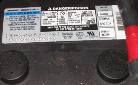
There's no such thing as a stupid question, right?  Please?  Above is the only label on each of Gizmo's main bank 8D batteries, and though it says AGM in big letters upper right, I'm not completely sure that they actually are Absorbed Glass Mat batteries.  Can anyone confirm one way or the other?  Then I might have a better sense of how well my battery monitoring system is set up, and what it's telling me...

Last season I mostly judged Gizmo's state of stored power using battery voltage, as I wasn't sure the Xantrex Link 1000 below was showing a true amp hour deficit figure (especially after this forum thread), and was not even sure what the total available amp hours were anyway.  I'm still not sure about the size of my AH bank account, to be frank, but I now think the -230 figure shown below is in the true deficit ballpark as I got it to about zero after extended charging via a Xantrex Freedom 2500 while the boat was hauled.  Typical voltage at this deficit state is 12.45v, though if I run the main engine with its 130 amp alternator, or the 6kw generator, battery voltage will hold for a while at about 12.65, even if I haven't chipped away much at that deficit.  Any red flags going up amongst the battery cognizanti out there?
   The big truths are these, unfortunately:  I know nothing about the history of this battery system prior to March, 2009;  Gizmo's former owner mostly kept the boat on shore power, anyway;  I almost never have access to shore power, haven't been cruising extensively yet, and hate running the noisy generator (another issue to be investigated); and I'm pretty dumb about batteries/chargers etc. overall...which is probably obvious.  For instance, am I doing serious power misering at the float just because I don't run either engine or generator enough, or because neither is charging the way they should?  The alternator seems to push about 60 amps for a brief period, than about 30-40 and the latter about 30.  Would the never-installed battery temp sensor for the Freedom 25 make much difference?
   I've gotten intrigued with adding a couple of solar panels so I might maintain a near full battery bank and still be moderately profligate with 12v when the boat's at home on its float.  But I'm also wondering if these batteries may need the equalization I understand is possible with AGM batteries, if they are AGM batteries??
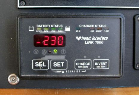
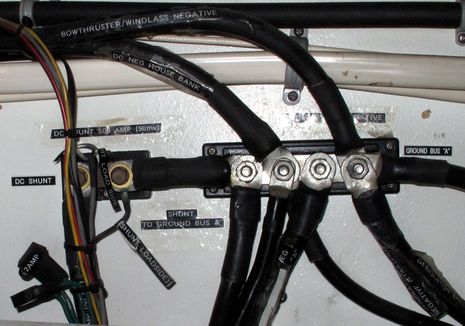
Gizmo_Xantrex_Link_100_cPanbo.JPGI'm also trying to track down what seems to be a .5 to 1 amp current flow through the Link 1000 when every switched circuit is off but the main battery switch is on.  I've found a few unswitched circuits but none tested seems to the culprit.  Can a clamp meter (I don't have yet) read low enough to help find the amp hour thief?  Also, if I cable whatever solar charge controller I get through the shunt below, will I be able monitor its output via the Link 1000 and its own monitor?  Sorry to be a font of possibly dumb questions -- and promise to write about something I know more about soon -- but, then again, I suspect a lot of Panbo readers are, like me, more tuned in to their electronics than the electricity needed to run them.  Guidance will be appreciated from those of you who have figured this stuff out.  
Gizmo_shunt_and_ground_cPanbo.JPG

Comments

Cognizati --Nice word. Can't wait to use it, but I think it is Cognizanti.
Thanks for your good works.
Roy

Posted by: Roy at July 6, 2010 2:07 PM | Reply

Doh! And I was already feeling short on cognitive skills. Cognizati is not a word, it turns out, and thus was edited out above. Thanks, Roy!

Posted by: Ben E at July 6, 2010 2:17 PM | Reply

I searched for "battery 8A8DM" (the model number on your battery) and they appear to be a Deka battery.

You can browser the catalog here:
http://www.dekabatteries.com/assets/base/0181.pdf

This page references your part number directly:
http://www.dekabatteries.com/default.aspx?pageid=468

Posted by: Patrick at July 6, 2010 2:39 PM | Reply

I think it's cognoscenti, no?

Dude... if you're never seeing more than 12.65 volts with the engine and a 130-amp alternator running something is not right. You need to see about 14 volts when charging to get anywhere. Even with AGMs, as I recall.

Time to load test those puppies. Then start pestering Nigel, IMHO. He's living in the hood again (Damariscotta, I think).

And you should definitely get going with some panels and wind dizzies if you never plug in and don't want to run your generator.

Posted by: Charlie at July 6, 2010 2:56 PM | Reply

Ben,

The info CCA/MCA reserve cap and charge voltages seem to indicate a AGM battery. Being sealed is another good indication.

The "Link" unit itself could be the drain to the batteries, as I am assuming that its powered from those same batteries. A clamp on meter will show low levels, however you need to find one of the low amperage units like the BK316 that has 1mA resolution on the 10A scale.

http://www.bkprecision.com/products/model/316/mini-ac-dc-clamp-meter.html

12.45V is indicating a charge between 50% and 75% (12.5V = 75% and 12.2V = 50%). A full charge is 12.8V or more. The charge rate should be 14.2V-14.4V for the bulk charge and then 13.2V-13.4V for float voltage.

Check and make sure that the charger is set for AGM battery profile as well as check to make sure that its charge voltages are correct.

Thanks,
Chris Hallock

Posted by: Chris Hallock at July 6, 2010 3:03 PM | Reply

Googled "Battery 8A8DM" and got this

Can't tell if the product picture is the same as your close up picture; but the website says its a Deka AGM battery.

Posted by: Biff at July 6, 2010 3:12 PM | Reply

Oh, a clamp meter only works with AC loads. To measure current for DC loads the meter must be wired in series with the circuit being tested.

Posted by: Biff at July 6, 2010 3:18 PM | Reply

They make clamp-on non-intrusive DC based meters as well, use them on the boat and car all the time. AC is more common, but DC are there just like the BK316.

Posted by: Chris Hallock at July 6, 2010 3:32 PM | Reply

It is a Dekka, it is an AGM, it is very heavy, my back knows it. Unfortunately no date stamp, but at an assumed 2year life of about four, or better, I'm not surprised at the resting voltage fully charged as you indicated. Chargers should be set for "AGM", They charge okay on "flooded" also, and they are difficult to hurt, and I have seen them take sustained charging rates of 100 amps without damage. I think you still have several good years of life in them, just periodically (maybe monthly) note the voltage level after running the alternators, and fully charging them. I alway recommend them as best option and bang for the buck, given the extended life and capacity. The big bonus is not having to crawl into some god forsaken hole to check the water. A little errata here. the AGM's were originally developed as fighter aircraft APU starting batteries. A lot of power, in a small space. No worries Ben (I will thinks about the amp flow issue)

Posted by: Bill Bishop at July 6, 2010 5:22 PM | Reply

As Charlie said, you definitely have an issue if you can never get above 12.65v. You should see voltages in excess of 14v on bulk charge with floats in the 13-13.4v range. Do you see 12.65v while charging? Is this measured directly at the battery, or have you only seen it on the Xantrex... errr... Heart?

There are two things that need to be done to see if it's a battery issue. You need to do an open circuit test and a load test.

The open circuit test is easy. Charge your battery to the fullest capacity it will take (and while it's charging, measure the charge directly on the battery - it should be AT LEAST 13v, but higher is "better"). Disconnect it from EVERYTHING (bilge, sensors, etc. - it should have bare posts) for at least 2 hours (48 hours is better). Then connect a voltmeter and see what the voltage is. 12.8-12.85 should be what you would see on a brand new battery. If it's significantly less (12.65, 12.5, 12.4, etc.) your battery could use a replacement.

Just because you pass the open circuit test doesn't mean the battery is OK. You then need to do a load test. Load testers aren't common equipment so see if you can find an electrician or a mechanic who has one. If you have a 100AH battery and you put a 50A load on it for an hour, the battery should be at a 50% voltage. If it's not, you could have a bad plate or something else wrong.

Unfortunately, AGM's GENERALLY can't be equalized, so if there is a problem with the battery it needs to be replaced.

It's normal to see the charger start at a high charge rate and then decrease. As a battery becomes more charged (at least the "old technology" batteries - Nigel can tell you about the new ones) it will accept less of a charge. A 90% charged battery will barely take any charge. When cruising, it's common practice to run your battery to 50% (the lowest you should go without causing damage - AGM's can go a bit lower than lead-acid) and then recharge to 80% to 90%. It doesn't make economic sense to run a generator to get that extra 10%-15% of juice.

As mentioned, Nigel is the expert at this. I would highly recommend picking up his book - Boatowner's Mechanical and Electrical Manual. It will walk you through every troubleshooting method out there for figuring out electrical issues.

With regards to using the Xantrex/Heart to measure charging on the batteries through a shunt when a solar charger is in the equation - that's how ours is hooked up. When the solars are generating, we see a positive flow to the battery (offset by equipment that's powered on). Our charger also shows the generated amperage on a display. Make sure you get a quality solar charger (and keep in mind that some chargers can cause noise on an SSB if you have one) and quality panels (the biggest you can fit).

By the way, I'm fairly certain my facts are straight with regards to the information above, but please correct any inaccuracies. I'm doing this off the top of my head as opposed to my usual (referring to Nigel's Boatowner's Guide).

Posted by: Chris s/v/ Pelican at July 6, 2010 5:26 PM | Reply

P.S. The reason for the temp sensor on the battery is so that you can avoid cooking the battery if it gets too hot. As the temp increases, the charger will decrease the charging level, decreasing the amount of energy converted to heat during the charging process, decreasing the risk of damage. Batteries are rather sensitive to temp.

Posted by: Chris s/v/ Pelican at July 6, 2010 5:35 PM | Reply

Hi, Ben -- I've got a relatively inexpensive clamp-on meter that will measure accurately down to tenths of an amp for both AC and DC:

http://www.extech.com/instruments/product.asp?catid=26&prodid=83

Do you have a stereo onboard? It'll have a "keep alive" circuit to hold memory for presets and such; that'll pull some current, especially if there's backlighting on the radio's front panel. The Link will pull some current, as well. And there could be leak from something like a bilge pump switch that's independent of the battery switch.

I agree on the voltage level when charging from any source; it should go up to 14 volts, but any higher and you'll cook your AGM batteries. You need to check to be sure that there's a switch setting on your shorepower charger (your Freedom 25) for the proper settings for AGM batteries; in addition, if your alternator has an external regulator, it needs to be set for the proper charging regime as well.

On the solar panels (and/or wind generator): as long as they're connected to the proper side of the shunt, their contribution of charging current should be reflected on the Link's display. And I would consider adding the temp sensor to the Freedom 25 if it's not too difficult; it can affect charging. But not as much as having the charger set to the proper charge regime.

Posted by: Frederick G Street at July 6, 2010 5:54 PM | Reply

Since I own a sailboat and live off of the batteries for months at a time while cruising the Bahamas, I have become the Cliffy Claven of batteries and power draw. I can entertain you for hours on end in a bar about batteries and power draw. Saying that a real battery expert would scoff at my knowledge and write me off as a mere amateur. What I have figured out is what works for me.

I currently have a Link 2000 with Trojan T-145 batteries installed. I have done the "what the heck is the 1-.5 amp draw dance many times. Here are some thoughts:

First check your AM / FM radio. The red wire should be switched through a circuit breaker. A lot of installers direct wire both the red and yellow wire so they can listen to the radio when all of the circuit breakers are off. What I have found is the AM / FM radio will pull about 1 amp even when it is turned off with the local power switch on the radio. Remember most of these units were originally designed to work in a car. The red wire is typically energized by the ignition switch.

Second, my link 2000 will only display as low as .5 amps. I am not sure about the link 1000 but I suspect it is the same. I can't get it to show anything less than .5 amps with the minor draws going on (clocks, LCD displays, refrigerator stand by, etc). I have not tested but I suspect the Link 2000 will show .5 amps just from its own power draw.

I would make sure the Link 1000 is programmed correctly. Especially the Peukert's factor (how fast a battery can charge or discharge), battery type, and Amp hour capacity of the entire battery bank. These will radically impact how the Link works. You can get most of the information from the manufacturer's website.

If all else fails place an Amp meter in line from each of the leads directly from the battery. Of course make sure everything is off at the time. You should be able to find out what is causing the power draw or at least narrow it down sufficiently. I am not sure the clamp on style power meters will work as low as you need to go. I have never used one on a DC system.

Posted by: Peter (sailboat owner) at July 6, 2010 6:01 PM | Reply

First, the battery surely looks like an AGM to me especially because it says AGM and is sealed.

I would definitely get a temperature sensor for the Freedom 2500. It does make a difference in battery charging. I'd also be prepared to replace the Freedom 2500 because there's a clock ticking for its demise. I've been through 2 of them in 8 years - there are much better system inverters available when the time comes. And it's coming.

Having run a Link on my boat on a mooring for months along with many months of living aboard, the -230 bank deficit is at best an estimate after about a week of being unplugged. It's not a surprise that it counts up to 0 when you're charged but that doesn't mean you're fully charged. I've found that you don't really get fully charged until you're plugged in for a good 24 hours. From that point, the amp hour total discharge will be good for a week. To be honest, I never even use it at all any more - I only look at voltage and amp draw with my monitor. It's about the only thing you can really trust over a long period of being off-grid.

Those bus bars and connections are crying out for some corrosion block spray. I would do that immediately and look around at other connections and electrical panels for similar needs.

Posted by: Jeffrey Siegel at July 6, 2010 6:15 PM | Reply

Batteries, like us get older. There are two points to consider here. The first is the output (Amperage of the two charging systems on a boat (110VAC Charger, and alternators). This is typically somewhere between 13.5 and 14.2 volts, and the amperage output level is managed by by the charging system's reading the batteries current voltage (check both the alternator, and charger output voltage). Depending on the systems, the lower the voltage level in the batteries, the more amperage is outputted). In other words, the higher the charge percentage (typically measured by voltage) the less output you have (amperage) from the charging systems, although this can vary considerably by system types, and set points. New batteries, for a while charge up to the factory specs, but as they get older, the 13.1 voltage level of a brand new battery erodes slowly down to lower levels over time. Getting old isn't for sissies. So if the charging systems are outputting at 13.5 to 14.2VDC, and the batteries only attain a fully charged voltage of 12.5-6 or so, the batteries are most likely just middle aged, but like me, there is plenty of life left. If there is some concern about this, a load test will tell you a more accurate story. My local West Marine has a load tester I borrow from time to time to double check.When I walk onto a boat, and the battery voltage is 12.5 esque, I move on to other issues.

I am always suspicious of both the Link 1000 and its second cousin the E-meter readings. Pull the power lead off the battery, and measure inline to see if voltage is present when all systems are off, and, and then try it with the battery switch off. Read 12vdc (as a metaphor) in either scenario? Something is still on, somewhere. The CMOS circuit on a radio only pulls milliamps, so the radio is most likely not a problem.

A couple more minor musings. Some alternators will not output until they reach a higher RPM level. So something to test is to start the engine, and run the RPM's up to about 1600, to make sure the alternators are excited, then throttle back to 800-900 RPM's, then measure the output. Measure voltage from the alternators main red lug, or if there is a regulator, from its output lug, and to the engine block, or equal ground. Good comments by everyone, the truth is out there, somewhere.

Posted by: Bill Bishop at July 6, 2010 9:06 PM | Reply

It is unlikely your batteries are in good condition, AGM batteries need some care (frequent verification charging system is putting out correct voltage) and feeding (fully charge once every month at least) or their life is dramatically shortened.

IMHO the benefits of AGM batteries over standard lead acid are minor vs. their inability to take owner abuse or charging system faults.

How about passing us a complete description of your charging systems including model numbers (e.g. alternator, smart regulator on your alternator, generator, shore charger), how much space do you have (specifically do you have space for the tall golf cart batteries that might make a lot of sense for you), your budget, and lets see what we can recommend as a group instead of an identical replacement to your existing batteries.

I am biased towards either golf cart batteries for simplicity or given you have a powerful charging system and a on the hook, the latest generation of batteries could make sense as they would dramatically cut down the amount of time you would have your (noisy) generator or engine running to charge them.

The time is cut down quite dramatically. These new batteries will accept the full 130 amp output of your alternator, right up to the point of being fully charged, where your existing batteries can't accept that much juice and therefore take much longer to charge.

Sound good ?

Posted by: Dan Corcoran (b393capt) at July 6, 2010 11:32 PM | Reply

Ben - As previously mentioned, you can get clamp-on DC current probes (I have two, one from Agilent, the other Tenma (cheaper, but maybe no longer available)). The challenge at low DC currents is to zero out the local magnetic field before clamping the probe on the wire. It is best to zero out the probe with the probe on the wire, in a fixed position and zero current in the wire, then hook the wire back up. If you can disconnect the wire, then a normal multimeter in current mode will be easier to deal with.

My primary use of these probes is to measure startup currents and associated voltage drops with an oscilloscope.

Jon

Posted by: JonM at July 7, 2010 12:34 AM | Reply

In my opinion, what is missing somewhat from the comments so far is the alternator and it's regulator. I hope to get a Balmar high output alternator soon and have done some research into alternator charging for "cycled" batteries.
A normal alternator such as in a car has a single voltage regulator (no "steps", no "charging regime", no "smart"). This must be set to at or less than 13.6V as anything above will damage batteries if this is present for extended periods while the battery is already full.
This generator and internal regulator is normally also what is mounted on a marine engine (such as my Yanmar and maybe yours) but it is not at all suited to a boat. In a car, the engine is running 99% of the time you use it. If you don't use it, no load is on the battery. Also, the battery is not cycled meaning never normally discharged below 95% (even that would be rare).
This may apply to the starting battery on your boat but we are talking about the house batteries here.
You are using the boat and putting a load on the house batteries far more hours that the engine is running so when it is running, you want a huge charging current, as much as a hundred times that what is charged in your car to replace the 0.005 Amp-hours that were used during the 2 seconds the starter engine worked. As I see it, the typical alternator with internal regulation is never meant to produce anything like the current that is printed on it. Mine has 80A printed on it but I doubt it has ever in it's life, even for a second, produced more than 30 amps (I have never seen more than 20 amps). After motoring straight for 10 hours, when I get to the dock and plug in, I see the current meter on the charger, also a Heart Freedom, go all the way up to 130 amps while voltage climbs up to 14.5V. One reason this is so is that at the alternator's low output voltage of 13.6V, the batteries will only accept a relatively small current. Just after starting, with the house batteries discharged to say 75%, the voltage should rapidly climb up to at the very least 14.2V, better 14.4V and in the case of AGM, even 14.5V. Only then will the batteries accept 20% of their capacity in amps. And only then are you able to replace a hundred or more amp hours on a short trip of an hour or so. The second reason is that alternators producing a high current get hot really fast and then limit the current to keep the temperature at bay.
The typical high output alternator (a) has external 4-step smart regulation that can be set to a battery type and such just like a mains charger and (b) is built to produce near the rated output when hot and therefore over an indefinite period versus just minutes with an automotive alternator.
Balmar for example, lists their alternator outputs both when cold and when hot.
Beware that you can only use up to 110 amp high output alternators with a single 1/2'' V-belt. Beyond that you need two V-belts in parallel or a multi-groove belt (which incidentally are common on modern Volvos while never seen on a standard Yanmar). So if your existing alternator has a single V-belt and the belt is not completely worn in mid-season after having been replaced in spring, that alone is proof that your alternator never produces 130 amps for more than a minute.
An alternative may be a sterling power device that tricks the alternator's standard regulator into believing the battery is totally discharged (dead) when it really is only partly discharged to get the alternator to ramp up as many amps as he can. I am not really interested in this method as it does not address the problems of temperature and belt.

In your special situation where the mains charger is mostly dead wheight and you may have tossed it if it weren't also the inverter, I would definitely investigate powerful and matched-to-the batteries charging from the main engine in addition to solar panels. My guess is that if you are in Maine not in Florida and use your boat often during the week and want to generate all of your power usage from solar panels you would have to cover most all flat surfaces which wouldn't help the looks of the boat. Remember you have a powerboat and how about harvesting 50 to 100 amp hours just when taking a short trip out of the harbor to watch the sunset on a weekday night?

Regarding the battery controllers, as Jeffrey has said, they depend on detecting a "the batteries are now absolutely and totally full" state. This is when they reset their internal counters. If they never really get that, as in your case, they work on dead reckoning and may be totally wrong. When they get to a fully charged state once in a while, then they train on the battery size, type, age and so on (and use the Peukert factor) to compute a "this many percent charged" number for you. But this all depends on the occasional "full" reset.
A standard alternator, because of the 13.6V cut-off, can never achieve that state, even if running for a year straight.

So how would you think about rekindling that love to your mechanic again? He should be able to set you up with high-output alternator and pulleys for a multi-groove belt.

And try not to use splitting diodes but a smart battery combiner (a relay) instead as the voltage drop of diodes makes things more compilcated.

Posted by: Henning at July 7, 2010 8:07 AM | Reply

Dan is right, more info is needed, the opinions are all over the map, including mine. How much time on the charger, any problems associated with starting, does battery life seem shorter than you would think it should be, or like it to be?

Posted by: Bill Bishop at July 7, 2010 8:08 AM | Reply

Wow, so much valuable information...thanks all. And whereas some of it is contradictory, I don't feel quite so dumb. (Though the fact that Googling the model # easily identified my Dekka AGM batteries did!) At any rate, now I have a to-do list for maintenance and further investigation, and I'm very grateful.

For clarification, the 12.65v reading is seen shortly after charging, but with a 200 AH plus deficit showing on the Link 1000. Charging voltage is about 14.3v. Also, I wired the stereos and am confident that they are completely off when the circuit is switched.

I'll be on the boat today, possibly installing that temp sensor and checking the Link/Freedom setup. I will report back.

Posted by: Ben E at July 7, 2010 8:21 AM | Reply

Ben I just spent last week re reading the manuals that came with the Sallyw and finally some of it soaked in. Do you have manuals for your alternator and its controller. The link unit has one that is good also.
I was able to adjust the charger to bring the battery up to its capacity in a few hours. Mine is a similar setup to yours. The manuals are a good place to start. I will be back Sunday to help.

Posted by: Allan Seymour at July 7, 2010 8:36 AM | Reply

Ben, A couple is things on AGM batteries. They can and should be equalized just as wet cells are, taking care since you can't boil off water and add when needed. Generally it should be done at 15.5 volts for 3 hours after you have brought them back to full charge. What the AGM manufacturers don't tell you is that if you do not recharge the batteries 100% after every discharge, you will shorten their lives each time. Not having the history of the batteries will make this a problem. You do have to take care and not overcharge the batteries, nothing will kill them quicker.
Your Bulk Charge should be 14.2-14.4
Your Acceptance should be 14.2-14.4
Your Float charge should be 13.2-13.3

Posted by: Capn. Chuck at July 7, 2010 12:46 PM | Reply

Ben,
Best advice I can offer - read the first two chapters of Boatowners Electrical and Mechanical manual (Calder). At the completion of this you will understand 95% of everything you need to know to troubleshoot your problem.
Also - check the voltage sense wire to the alternator. If your alternator output is directed to the house bank (as it should be), the sense wire should also be sensing house voltage. Many original installations had the alternator output directed back to the start battery - if the alternator is still sensing a good start battery voltage, the internal regulator will not ramp up the output to recharge your depleted house battery. Good luck,

Posted by: Grant at July 7, 2010 12:48 PM | Reply

Concerning the small positive current registering on your Link monitor: All batteries have a small parasitic resistance which cause an unused battery to go dead with time. This parasitic resistance varies with temperature. I suspect that the small current being registered on your battery monitor when everything is turned off, provided you don't have any rogue circuits that the monitor can't see, is the current associated with the parasitic battery resistance.

In my boat (700 AH worth of battery banks), my Link 10 indicates 0.3 A with everything turned off and the batteries fully charged during the winter. In the summer, 0.7 A is indicated.

Posted by: Ralph M at July 7, 2010 3:01 PM | Reply

Well, if the Link 1000 is way off on AH deficit, as Jeff and others suggest possiblem, I may be in better shape than I thought. I ran Gizmo for about 4 hours this morning, mostly at low RPMs, but that doesn't seem to effect alternator output. Which, by the way, is a Prestolite Lerce-Neville 8LHA207OVB, rated at 130 amps, no separate regulator, probably none too smart.

At any rate, the two 8D bank consistently took a charge at 14.45v or 14.3v, depending whether you're looking at the Link (higher) or the voltmeter on the Paneltronics panel. Positive amperage flow on the Link started at about 20 but quickly went to about 10. At the end of the testing and channel buoy charting (;-) I was doing, I shut down most all loads while the engine was still running and saw 14.5v and 14.4v charge voltage on the two meters.

Once shut down, the main bank showed 13v for a while, but now, 2 hours later, with only the 2 amp load of the Tracer police car computer, it's at 12.8v. The Link says I only gained about 35 amp hours during that run time, and still have a large deficit. But if, in fact, the batteries are better charged than it thinks, don't all these numbers make more sense? I've also seen higher charging currents in the past, when the voltage was lower.

At any rate, a smart regulator certainly might help me make more power quicker, and solar panels also make sense for how I use this boat. But I will investigate further; more to come.

Posted by: Ben E at July 7, 2010 3:23 PM | Reply

Ben do you have a Balmar alternator and the corresponding controller? The controller can be setup for various batt types and comes with a excellent book. It adjusts all three charging parameters. The link does not draw anything and is the key to what is going on with the charging system. See ya soon.

Posted by: Allan Seymour at July 7, 2010 3:55 PM | Reply

Those charging voltages sound great. As does the surface voltage when the batts have been idle for two hours. I'd say the batteries are basically healthy (though a load test never hurts). But you'll have to run the engine a long, long time to get them up to a full charge, even with a 130-amp alternator.

An even bigger alternator wouldn't be a bad idea. Then, as mentioned, get some alternative power sources running. With the panels and wind dizzy I have on Lunacy, the batteries usually get all topped up nice if I leave the boat idle for just a couple of days in sunny and/or windy conditions.

I NEVER plug in to shore power.

Posted by: Charlie in reply to Ben E at July 7, 2010 4:13 PM | Reply

If your "resting" voltage after two hours is 12.8v, I'd say you're probably just fine - 12.8-12.85v is the normal voltage of a fully charged AGM. You'll see a residual charge voltage above that for a while after you stop charging. I had the Link 1000 and every so often it would go out of whack. If you download the manual from Xantrex's website, there's a way to reset the AH used. The voltages you mentioned during charging are well within spec, and the positive amperage flow is normal for an almost full battery. I'd say your Link just needs to be reset and you'll be good. The only other thing I'd check, after resetting the Link, is how quickly your voltage drops when you put a load on the battery. In other words, turn a whole bunch of stuff on, take a look at what the Link says you are drawing, wait an hour, measure your voltage, and see if everything is aligned.

The solars are great for keeping your batteries topped off when you aren't around - especially when you're on the hard. We can run our refrigeration and several instruments off of our panels and still net positive. I have no affiliation, but eMarine Systems (http://www.emarineinc.com) knows a lot about alternative energy systems. I visited their offices when we cruised through Ft. Lauderdale and was impressed with their knowledge.

Posted by: Chris s/v/ Pelican at July 7, 2010 4:16 PM | Reply

Ben, What regulator are you using?
East Penn has an excellent technical manual on VRLA batteries. http://www.dekabatteries.com/assets/base/0139.pdf

Posted by: Alden Cole at July 8, 2010 5:25 AM | Reply

Ben,

"mostly at low RPMs, but that doesn't seem to effect alternator output"

FYI, here's your alternator:
http://www.prestolite.com/pgs_products/specs.php?item_detail_id=802&item=8LHA2070VB&product=Alternator
Lots of good stuff there. If you click on the Output Curve link, you'll see that output IS actually dependent on RPM, although it's a fairly steep curve. Also note this is alternator RPM, not engine RPM, which typically runs the alternator 2.5 - 3 times faster than the engine.

Even so, getting those 8D's topped off while running is going to take a while, the high resistance and correspondingly low acceptance rate result in a long charge time for that last 20%.

I agree with Chris that your fundamentals all sound good, I think you just want to reset that Link 1000 and spend a little time in the Link manual. It's really a pretty accurate instrument if it's installed and programmed correctly.
Cheers,

Posted by: Grant at July 8, 2010 11:49 AM | Reply

Ben
You definitely need to utilize a solar cell system for hanging on the hook/mooring instead of the dock. As Jeff Siegel and other said above, your batteries will never fully charge the last 10% unless they are being charged over a longer period of time than running the genset or engine. Docking and plugging into the power hose for a day or more is usually required to get that last 10% charge. That said, if you had a solar panel, the panel would perform this function (also need a regulator for the charge line from the solar panel). This would be a wonderful project for you to undertake and write about. I'm surprised you havent gotten into this yet !
As you get into this, you will quickly realize that your initial question about whether or not you really have an AGM battery leads to lots more discussion. The discussion is about your complete DC system: storage, usage, and charging. Nigel Calder's book is really great in this area.

I would add a solar panel to my own boat if I had a place to mount it. You could have your panel set up as a portable system in which you store it in the lazarette locker when you are using the boat and pull it out and plug it in when you put the boat back on the mooring.

R.

Posted by: Ralph Yost at July 8, 2010 4:29 PM | Reply

I've definitely been looking into solar panels, Ralph, and am lucky to have a great spot for a couple on Gizmo's extended cabin top. I'm even toying with ideas for a manual tilt and turn tracking mount. I'm also in the process of switching over to LED interior lighting. But it's all happening in bits and pieces as I have other projects underway, too, and really do intend to take a long cruise in a couple of weeks. "So many gizmos, so little time!"

Big thanks to Grant for finding all that literature on my alternator, and to Alden for the Deka tech manual (which others have sent via email and is now printed and on board). I should have learned more about my batteries and charging system sooner, but I procrastinated. All of you have been a terrific help. Thanks!

Posted by: Ben E at July 8, 2010 5:07 PM | Reply

On a Jarvis Newman 46, I have Leece-Neville alternators modified by Lewco Electric for the Ample Power Smart Alternator Regulator (SAR) ver. 3. I have 2 engines and 2 Leece-Nevilles charging one big house bank (over 1000 amp hours of T-145's), so I also use Ample Power's dual alternator controller (DAC). The SAR ver. 3 is one of the best pieces of equipment on the boat, as is the DAC. Gone are the days when we'd spend some hours powering somewhere, to arrive and realize we needed to crank up the generator to charge batteries. I can charge at a rate sufficient to cover inverter loads AND charge batts simultaneously. I don't know why anyone would mount a different alternator regulator unless spending as little as possible is of primary concern.

http://www.amplepower.com/products/sarv3/index.html

Posted by: ChipD at July 9, 2010 2:18 AM | Reply

Many AGM battery builders will allow you to equalize. East Penn is not one of them. They tell you that you will void their warranty and liability. One of the concerns is thermal runaway (read Ugly boat fire). We have had great success in reconditioning batteries as old as 10 years and at 5.5 volts. It is tricky but doable. We have found all the major manufactures have slightly different charge preferences for voltages and time. Here is the East Penn poop sheet http://www.dekabatteries.com/assets/base/0139.pdf
A great place to start is the AMPLE power primer
http://www.amplepower.com/pdf/primer/Ample_Power_Primer.zip
and be sure to break the batteries in. We have found no battery charger manufactures that monitor and can keep accurate track of power in/power out without losing count.

Best Regards to all
Bill

Posted by: Bill Taylor at July 9, 2010 1:50 PM | Reply

Ben, hard to believe you don't have a smart regulator to go along with those really expensive batteries. AGM batteries will be damaged by an alternator without the regulator to provide the three stage charging they require, but a standard alternator does not provide. How did you determine you don't have? Don't expect the thick alternator output wire to run to the regulator, instead look for small gauge wire running to the regulator which in turn is connected to the battery.

You wrote "The alternator seems to push about 60 amps for a brief period, than about 30-40 and the latter about 30". As alternators don't push electrons, I take what you wrote to mean "the batteries seem to pull about 60 amps for a brief period, then about 30-40 ..." That is very little for a pair of 8D batteries! This seems to indicate either the batteries are fully charged (which you seem to doubt) or the regulator is not set or functioning correctly.

Solar panel technology is going thru radical changes that have not reached the marine market yet. The effect is a trippling of power for the same surface area. Probably not a bad thing to let that purchase hang out in the future.

Posted by: Dan Corcoran (b393capt) at July 10, 2010 8:33 PM | Reply

Seems to me Dan makes a lot of sense. Especially as Sallyw is set up like he says and it works fine. The batteries were installed by Andy Fegley who was written about in last Soundings mag. Ben I am here in Camden harbor and would be glad to show you his setup.

Posted by: Allan Seymour at July 11, 2010 8:58 AM | Reply

Hi Ben

I've got a similar setup to you. I've also got overly concerned about batteries condition. Below are a few observations/experiences.

My Link shows 0.5A with everything off. Seems to be the draw of the monitor itself.

The final charging stage is very slow. I added 128W of solar with a $100 BZ Products MPPT regulator which has solved the issue of how to float charge when away from shorepower.

Batteries need to be rested (no load whatsoever) for an hour or more to get a true reading. Battery temp affects how to interpret the reading by quite a margin. Most figures quoted are for batteries at 25C - google the graphs for Lifeline AGMS to see readings for 10C/15C etc.

Getting a battery fully charged, then applying a known load for a day, then resting and remeasuring is a sure way to get a real world view of the charge it holds. I feared mine were history until I did this.

After doing the above test, it's useful to gather data to understand the voltage readings under load. ie so you know that with a 5A and the Link showing 12.0V you've got X% remaining.

Good luck.

Posted by: npf1 at July 12, 2010 7:14 AM | Reply

I believe the link is .015 amps or less, at least for the model I have, the Link 20.

Looking for unexpected power loads, here are a few ideas beyond the stereo memory circuits and link style monitors, based on my personal experiences:

1) I was surprised that my inverter, while turned off (e.g. off, not standby), draws a small amount of current. Fortunaly the builder has a cutoff switch wired between it and the house battery so I can completly disable.

I forgot how much the inverter was drawing, but it far exceeded the memory circuit in my stereo.

2) On Beneteau sailboats there is a remote control for some misc. floor lighting that nobody uses. I think it just looks neat at the boat shows. The remote itself comes with the key ring. The receiver on the boat is the part that draws the power from the house battery.

3) For some reason my shore charger allows some power to flow between the starter battery and the house battery. As some loads on my house batteries, like those mentioned above and below take some juice, my starter battery ends up with a slightly higher voltage that finds its way out.

4) Not a surprise for me, but if you have a galvanic isolator on your boat, beware some of them have a failure sense circuit that is powered by your battery.

5) Bilge pumps draw power in a couple of different ways
a) Lighting up a light on your DC panel showing they are powered
b) If solid state water sensors (rather than float switch) they need a little juice
c) Some pumps, cycle once every few minutes (I forget why)

6) Some DC panels have back lighting, be sure to keep that switched off not just for the power consumption, but also those back lighting bulbs begin to burn out after 500 hour of use and won't work anymore.

I am sure I missed a few things, but the point is that stereo memory circuits are not the only culprit.

Posted by: Dan Corcoran (b393capt) at July 12, 2010 9:46 PM | Reply

you can get a less expensive clamp on DC AMP meter from Craftsman.

$60.00

Model# 82369


400 AMP AC/DC

I like mine

Posted by: Willi at July 13, 2010 9:56 AM | Reply

Willi, an inexpensive DC clamp meter can be a really great tool for most uses on a boat if it can do well to a resolution of +/- 0.1 amps at small loads, like tracking down whats slowly draining a battery.

Does this craftsman, about this accurate in your experience. ? (E.g. if you measure a load of 0.2 amps using a standard in-line ammeter, does the clamp on come within +/- 0.1 amps ?). Same for 1 amp or 2 amp loads?

Posted by: Dan Corcoran (b393capt) at July 18, 2010 11:13 PM | Reply

Dan visited Camden, which was nice, and he brought along his Amprobe LH41A clamp meter, which was impressive (though pricey). It helped confirm a few issues on Gizmo, plus Dan had already guessed one of my steady drains -- unswitched main panel lights -- and he found the circuit for me.

At any rate, there's a link to the Amprobe specs here:

https://www.panbo.com/archives/2010/02/dans_boat_tools_the_battery_operated_kind_.html

It claims DC amperage resolution below 4 ampa at 1 mA. I found a manual for the Craftsman, but can't seem to find a resolution claim:

http://www.sears.com/shc/s/p_10153_12605_03482369000P

Posted by: Ben E at July 19, 2010 7:16 AM | Reply

(Updated) Willi, a DC clamp meter can be a really great tool on a boat, but the ones I have found are either expensive (like the LH41A), or are unable to measure small DC currents.

For tracking down small loads that are draining a battery, you don't need something as accurate as the LH41A (1 ma in 4A range) but a clamp on does need to be reliable in the 10mA to 25 mA range to find leaks. (note a 40mA leak will drain 1 Amp Hour of energy from your battery each day)

Is the craftsman about this accurate (10mA - 25mA in low range) in your experience? (E.g. if you measure a load of 0.04 amps using a standard in-line ammeter, does the craftsman clamp-on detect it with enough vigor to convince you it's not a ghost reading from nearby magnetic fields ?).

Posted by: Dan Corcoran (b393capt) at July 19, 2010 9:58 AM | Reply

Happy to report that I've been running Gizmo's Sea Frost 12v refrigeration for a week now, along with a careful selection of lighter loads, and the AGM battery bank is doing fine as long as I run the main engine for a couple of hours a day. The Sea Frost can draw as much as 10 amps sometimes, and I've driven the bank down as low as 12.2v, at which point I've seen alternator current flow as high as 115 amps (at about 13.7v). It almost seems like there's a smart regulator at work, though neither Dan nor I could find it.

At any rate, now that I view the Link 1000's amp hour calculations as only a short term guide, I think I've got a fairly decent house bank. And thanks to you all I learned a lot about battery management along the way. The next phase will be designing and installing the solar panels that I think can make better use of the battery bank's top end, and help a lot when the boat is moored.

Posted by: Ben E at July 28, 2010 1:51 PM | Reply

What a fun visit to see Gizmo and have my hands on Ben's beautiful floating laboratory. I especially liked the PC at the helm below, and the BR24 radar on the Simrad plotter. Unbelievable how well the radar image represented the size and pin point location of the 24+ mini piers around the harbor. I also understand it saw my rubber dinghy, sans engine, as I approached.

But onto a mystery I have to share.

Indeed there is no smart regulator on Gizmo, the alternator all on it's own puts out the much higher 14.4 volts (did I remember that correct) needed to quickly charge batteries.

Standard automotive alternators put out a voltage that is too low to rapidly charge an AGM battery. Adding an external smart regulator to a standard alternator, brings the voltage up to a higher voltage, which in turn causes the battery to draw more amps of power from the alternator and charge more quickly.

Another feature of a smart regulators, beyond optimum charging times, is to protect sealed batteries from over charging. With standard lead acid this isn't much of a problem, the hydrogen boils out and is replaced by adding water manually. With AGM batteries, escaped hydrogen isn't replaceable, leaving permanent damage.

A smart regulator applies different voltages to a battery based on its estimation of the current level of battery charge and the temp of the battery (using a probe). A typical AGM "profile" (source Balmar.net ARS-4 manual) is as follows sans temp compensation:

1. Bulk Charge = 14.4 volts, used to rapidly charge the batter.

2. Absorption = 14.2 volts, used to top off the battery

3. Float = 13.4 volts, used on a fully charged battery so that it draws just a trickle plus the current needed by any loads on the battery.

With Gizmo, there is no Absorption of Float voltage. What has me confused with Gizmo is why the previous owner didn't install a smart regulator at all, and why on the surface there seems to be no consequences to that as it would seem the choice of installing an alternator set to 14.4 volts (near the absolute max voltage an AGM battery can accept) is a shore fire way to cook some expensive AGM batteries in a couple of years or less.

I say, no apparent damage, as during my short visit we didn't run an extensive test, but did place a C/20 load on the batteries (with engine off) and measured a voltage of 12.7, which is not to shabby.

As an aside, I do believe the reason the Link 1000 isn’t resetting to zero (that's what started the original postt) is that the batteries continue to draw to much current, at that 14.4 volts, from the alternator for the Link 1000 to register that the battery is fully charged. Not a problem if the voltage was floating at 13.4 However, there could be other causes I did not investigate, such as not correctly setting the size of the battery bank in the Link. Ah time was short, and there was so much to see.

Any thoughts why these batteries are not toast ?

Would you advise Ben to change to install a smart regulator, or just leave the power system alone and spend more time testing products for Panbo ?

Posted by: Dan Corcoran (b393capt) at July 29, 2010 6:19 PM | Reply

In my own best interest I think Ben should forget about his batteries and test products - preferably those that I am most interested in (charting software, PC radar, electronic charts, N2K-PC integration and N2K instruments and sensors)!
But in the best interest of Ben's batteries, I would suggest to invest in a smart regulator. The need for this has been discussed from all angles above.
My idea as to why the batteries aren't toast is that the engine/boat isn't operated for very long periods at a time and not in high temperatures.
If Ben started to complement his income by fishing the new foundland bank where each trip is 2 to 3 weeks and the engine is run continuously for that time or if Gizmo would visit Florida in Summer and make 12hr + trips, I think that the batteries would deteriorate more quickly than they have.
However, I also think that if the charging voltage hadn't been set this high, the batteries would already be damaged from suplhation due to undercharging.
I also agree with your opinion on the battery monitor being reset. Details of detecting of the "full" state will vary from model to model but it will be something like:
- voltage is at float-level (13.something)
- current has been small (less than x% of capacity) for n time
In Ben's position I would look into external regulators that can be retrofitted to Gizmo's alternator (need to find out if the alternator is n- or p-type for this), compare this to the cost of a new Balmar 150A bundled with external regulation plus mounting hardware, belts, pulleys and put this on my "winter 2010/2011" list.

Posted by: Henning in reply to Dan Corcoran (b393capt) at July 30, 2010 6:41 AM | Reply

When using a clamp-on DC ammeter, you can increase the meter's sensitivity by passing the wire through the clamp several times. If there's enough slack in the cable, make a coil and clamp through the center of the coil.
Two turns through the clamp = 2X (1A reading = 0.5A actual)
Ten turns = 10X (1A reading = 100mA)

This can be tough with heavy battery cables, but it's worth a try.

I've found the Link AH calculations get pretty far off after a few days of heavy use, especially when using my solar panels to partially recharge. There are charge efficiency factors in the Link that you may be able to adjust for better accuracy, although I haven't tried this myself.

Posted by: Paul at August 17, 2010 11:05 AM | Reply

Ben, I noticed you are using a Freedom 25. If you are using the temperature compensation capability (vice setting a battery temperature) be aware if the sensor fails, it can send the Freedom a battery temperature of 1 deg F. The charger will then send Accept and Float voltages of around 15 and 14v. This just happened to us while escaping the heat in Maine for two weeks (boat on the Chesapeake). While people on the dock heard the alarms, they did nothing. Result -- 600Ah of Deka 4Ds fried. One boiled and all copper and bronze below is black. All vinyl discolored.

Have requested help in finding a new temp sensor from Xantrex as there appear to be none in the supply chain. In the mean time, we will operate the charger in the manual temp set mode, and if we do get a new sensor, we will always switch to manual when leaving the boat -- or perhaps I should say will only use auto sense mode when we are aboard.

While going through the post problem diagnostics, I logged battery temps every 10 minutes while recharging on the standard three stage profile and the hottest battery (the one that boiled and may now have an internal short) only went from 87 to 94 deg F. Max amps were 116 and max volts 14.2. So while I can see how the temp sensor helps fine tune the profile, I'm not sure the labor it saves is worth the potential failure cost. These batteries had another 5 years at least.

C

Posted by: Chris at August 25, 2010 10:14 AM | Reply

Leave a comment