The Wizard, first impressions

... written for Panbo by Ben Ellison and posted on Oct 28, 2008

 Wizard_prototype_Oct_cPanbo

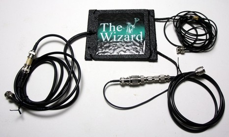
A sample of the intriguing but controversial Wizard antenna arrived yesterday morning and I was able to do some testing before hitting the road for Fort Lauderdale. If I had to put the results in three words they’d be: disappointing but tentative. Before the details, check out the bigger image , which goes along with a more concrete description (that came with the sample) of the marine Wizard’s purported capabilities. That RG-58 cable with a BNC connector coming out of the left side will support a 25 watt VHF radio while the two RG 174U cables on the right (one BNC and one SMA) can purportedly handle AM/FM, WiFi, GPS, Cellular, Sat phones, and UHF/VHF, all transmissions limited to 5 watts. The various added connectors and patch cables are what I had to do to hook the Wizard to VHF and Class B AIS, and the unfortunate lash up at bottom right is one of the reasons I say “tentative.”

* 25 watt VHF: Using the Lowrance LVR-880, I did A/B/C tests with an 8’ 6dB Glomex stick mounted about 30’ over the test area, a Shakespeare 3’ 3dB stainless whip mounted near the radio, and the Wizard (also nearby). The number and quality of WX stations received were in that same order, though there wasn’t a startling difference from Glomex to Wizard. Ditto for a brief transmission test I did with “Sparky”, a young radio and harbor enthusiast you’ll hear more about. Sparky and I were about a mile apart, with lots of wet trees and buildings in between; he could detect a slight quality difference as we moved through the antennas, but the Wizard did work.

* Testing the 25 watt line with a Shakespeare ART-3 was more troubling. The Glomex tested at 28 watts with 1.2 VSWR, the Shakespeare at 26 watts with 1.3 VSWR, and the Wizard at 18 watts with 2.9 VSWR. I tried moving the Wizard around (per instructions) but only saw a little variability.

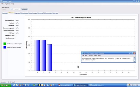
* Class B AIS (GPS and 2w VHF): Using the Digital Yacht AIT250 and ACR Nauticast B transponders, I did A/B tests between the ACR antenna set and the Wizard. Not good. The screen shot below (bigger here) shows about the best GPS reception I got, trying two locations, and the Wizard never generated a fix. By contrast the ACR GPS antenna let the transponders lock on to 7 to 11 satellites. Of course the units wouldn’t transmit without a fix, but they did receive another Class B that was very nearby. Now note that the GPS signal was traveling from the Wizard through that 5 connector misfortune seen above, but it’s continuity check out fine.

* WiFi (and more): I didn’t have the right connectors. Friggin connectors. PL-259, BNC, SMA, RP-SMA, TNC, RP-TNC, N…I saw all those in just the VHF, Class B, and WiFi gear I’d like to connect to the Wizard. And then there’s cell phones and amps. I didn’t have much luck at Radio Shack but have a bunch of adaptors coming from data-alliance and ShowMeCables.

And I have questions to ask at AMT’s FLIBS booth (#805). I was surprised, given the no-line-of-sight claims, that the company recommends installing the Wizard as high and as unobstructed as possible. So why the short cables and lack of mounting system? What’s a Wizard going to cost? And what’s up with the GPS reception?

Wizard test w DY Class B 

Comments

VSWR of 2.9 in the marine band?? Not so good. That’s a good way to burn up the finals in the radio.

Without amplification built-in for the GPS antenna, and the cable losses at 1.575GHz its amazing that you got any signal. I have had many Garmin handheld units over the years and any of them with an antenna that has a BNC connector if you extend that cable by just a feet it won’t work properly. If you use an amplified antenna on a long cable run it will work fine. Keep in mind that for instance Garmin supplies +5VDC on the antenna output. I am not sure if the antenna is open at DC voltage or shorted to ground, but if the later it will cause the GPS to error as it detects the short.

It would be nice if they publish the center frequencies of each antenna input/output. Without this information I can see a lot of burned up transmitting devices.

Just a gimmick. Would you want to trust this antenna offshore and in an emergency situation? Height is everything in line of sight communications, and with a very ineffective radiator as shown in the VSWR readings its not going to work well.

Thanks,
Chris

Posted by: Chris H at October 29, 2008 8:34 AM | Reply

I'd be a bit worried about damaging the front end of a GPS receiver here. I wonder what the isolation between the VHF and GPS connections are? 25W is an awful lot of RF power to be sticking up the sensitive end of a GPS receiver, could easily destroy it....?

Many marine GPS receivers need an antenna with reasonable gain (say >15dB). I doubt this 'antenna' includes that which probably explains the poor GPS performance.

Posted by: marinate at October 29, 2008 11:32 AM | Reply

I haven't tried that yet, Marinate, and when I do it will be with a GPS I can live without.

Chris, I think that all these Class B GPS antennas are completely passive. I have certainly used them interchangeably without problems.

PS Fort Lauderdale is not all doom and gloom so far. In fact, there are some very interesting new electronics being introduced. Stay tuned.

Posted by: Ben at October 29, 2008 1:36 PM | Reply

It would be very interesting to try this: try transmitting into an equal length of coax cable with a 50ohm dummy load at the far end. How does marine VHF transmit range compare?

Or - compare transmit/receive range against a marine VHF handheld. A handheld radio's short flexible antenna is very inefficient. I wonder which antenna would turn out to be better? If the wizard does no better, save yourself several hundred dollars and stick with conventional antennas.

The 2.9 swr is odd, if the antenna is intended for marine use. You'd expect them to have optimized the design so that the swr is lower. In the face of swr above 2, some radios will fold back RF output power, perhaps dramatically.

The 2.9 swr also raises another issue, if the antenna is intended to cover a very broad range of frequencies, as the website suggests, then what are the SWR curves? For what frequency ranges is the SWR below 2? Below 3? SWR is not the be-all/end-all of antennas, but an interesting point of information.

Very interesting that the booth folks suggested mounting high, as this makes perfect sense. They sound pretty reasonable, in comparison to the website.

Posted by: Robert at October 29, 2008 7:26 PM | Reply

I was curious about the IBEX innovation award. So, I emailed the IBEX folks and asked about their process for selecting winners of the innovation award. The response I got said, in part:

"The judges are not allowed to test a product nor do they have the time while on-site. The judges and I rely on the statements made by the entrants when they entered the awards, as they have to state on their entry form that their claims are true."

"In the case of the antenna, the judges saw a demonstration on AMT Revolution's computer that showed that it was picking up only two signals in the hall. When they connected up the antenna it picked up eight or so signals. They also had a yacht captain who said that it had enhanced his yacht's signals enormously. The voting on The Wizard being innovative was unanimous."

For an industry trade association conference, this is probably about as thorough an evaluation process as can reasonably be expected.

But - keep in mind that the limits on that Innovation Award. At best, it shows only that the antenna is capable of actually receiving signals in an RF dense environment of an exhibit hall where people are using marine radios. Oh yes, and one person talked about how much he liked it.

That makes the Innovation Award interesting, but I'd want to know how much the judges know about RF and antennas, and just how rigorously they approached their job.

The IBEX press release does not exactly inspire confidence with the one quote concerning the AMT antenna: “Fractal math, magnetic spheres, Tesla—this product is something you’ve never seen before,” explains Clarke." Ummmm... OK - but what does that actually mean? What has Tesla or magnetic spheres got to do with anything?

Posted by: Robert at October 30, 2008 11:17 AM | Reply

Questions I'd ask the AMT folks if I were in Ft. Lauderdale:

- The antenna has three cables, different sizes different connectors. What applications exactly were these intended for?
- Do you have antenna pattern plots, both azumith and elevation? The website mentions Motorola doing pattern testing for the 500MHZ to 1GHZ range. Show me.
- Do you have SWR curves showing the SWR for various frequencies? Show me.
- Explain the "not limited to line of sight" statements on the website?
- How much isolation between ports, expressed in db?
- Can I run maximum transmit power into the antenna while simultaneously using it as a receive GPS antenna? Run maximum transmit power in, while using it as an antenna for FM broadcast reception? Or do I need some external filtering? There have to be some combinations of simultansous TX and RX that won't work. For example, if you had two marine VHF radios connected to one Wizard antenna, transmit with one at 25 watts and the other would almost certainly go stone deaf.
- Transmit power limits by frequency? For example, if it will take 25 watts at marine VHF can I put 25 watts into it at 15 MHZ or 1.5GHZ?
- The website claims this antenna works in the HF range. Explain what testing backs up the idea that this antenna has any reasonable efficiency in the HF range? What power limits?
- Actually, the website claims operation from "20hz to 6ghz" - Can this antenna be used for marine HF ssb, at say 2182khz? What test results back this up?
- Are there field strength studies that compare the antenna to some reasonable reference, for example a half-wavelength dipole at a given frequency?
- The website says the antenna uses "antenna polygons" - What does that mean? Some reference to the science behind that would be nice.
- The website says the antenna features "individualized pixel elements" - What does that mean?
- That government contract with the "dismounted battlespace battle labs" mentioned on the website, tell me about the testing that was done, Receive only? Receive and transmit? Frequency range? Power levels? Two way voice? GPS reception? Informal testing? Laboratory testing on an antenna range? What measurements? Where is the report of the testing?
- When will the FAQ and manuals section of the website be active?
- Why is the only commercial dealer an outfit that sells batteries? Why no communications dealers or RF related businesses?

Posted by: Robert at October 30, 2008 11:59 AM | Reply

Ben-
First and foremost - thanks for the tests - nicely done considering the hassles you faced. Next - in general- VHF communications loose 6 dB in power each time the distance from the original transmitter is doubled. So loosing 3dB between the first two VHF antennas should have had only minor impact - and that is what you observed.

Next the VSWR of 2.9:1 corresponds to a return loss of about 6 dB - that means 1/4 of the transmitter power is reflected by the antenna back at the transmitter - vs your other worst case VSWR of 1.3 the reflected power is 18 dB down or

So in theory - loosing 25% of your power on transmit ( 6 of 25 watts) just lost 50% of your transmit range (6 dB loss is half the communications range). So go get Sparky to take his boat out of the marina a couple miles and you'll see the loss of signal.

Chris was on the right track about passive GPS antennas. Each foot of coax length raises the noise figure of the receiver. Depending on the length and the coax loss per foot plus connector losses - some passive systems, with enough loss will fail outright. Its the old "barge Vs narrow sailboat" comparison - they both float and both serve as boats. One more efficient than the other.

He is also correct that some GPS receivers do put +5 or so on the center coax line to power a remote antenna with a low noise amplifier - specifically for GPS receivers that would be remoted from the antenna. Chartplotters have the entire antenna, amplifier and receiver in the same module - with power obviously applied on the coax. Handheld or self contained (AIS for example) GPS systems that use remote passive antennas would "work" just fine - if - the coax losses are low. A better system design - though more expensive would use a remote active antenna with low noise amplifier.

Ben your last comment about the requirement to mount the Wizard high with no means to do so is only the first comedy of the antenna.

1) What about the other two coax leads coming down from the antenna? If the antenna is somehow mounted high it will have to be oriented flat - as shown in your photo to keep it vertically polarized,

2) The other coax lines are going to get long and the losses at those GHz frequencies for WiMax and GPS will be significant.

3) The poor GPS reception is a very good indication of bad efficiency: A) GPS signals are RIGHT CIRCULARLY polarized - and the Wizard is VERTICALLY polarized. That means in the very best case the Wizard throws away 3dB (half) of the power it receives. But in this case the two planes of the X and Y components of the GPS circular polarization are 90 degrees from the vertical orientation of the antenna E field ( The circular polarization is oriented parallel to the earth surface) so far more loss would result. You need to take the Wizard and stand it on edge - then test the GPS reception again - it may improve a bit.

But if you orient the Wizard on edge (vertically vs flat on a table) it will kill all other Vertically polarized applications (virtually all other claimed apps). So if you get Sparky back at the marina - tip the Wizard on edge and see if you loose signal - rotate it around to try to improve reception - but no real benefit will result.

Ben - just a few more simple tests should put this Award Winning Antenna into the dust bin where it belongs - enjoy the boat show!!

Posted by: DaveV at October 30, 2008 4:08 PM | Reply

Ben,
I suspect that this is basically a fractal antenna (similar to what is used in an item such as the I phone:--GPS, Cell phone, Bluetooth, and wifi all in one antenna. However, in this case, the frequency of the various functions are fairly close. Polarization can be handled by a flat Fractal antenna. There is a fair amount of information about Fractals:
http://www.fractenna.com/,
http://www.fractenna.com/nca_faq.html,
http://www.hbci.com/~wenonah/cfa/fractal.htm,
and of course on Wikipedia...

If this is a fractal--then I would still be suspicious about claims for all of the various frequencies, unless it was designed specifically for those, but it may have a wider lattitude of SWR than a confential linleal anetnna.

Regards,

Bob Austin

Posted by: Bob Austin at October 31, 2008 6:48 PM | Reply

Hey whats happening here - I just read quiet a few commenst from folks that assumed Class B AIS antenna's are passive - not true ! There is at least 5 volts DC on the line to fire up an RF amp inside the GPS receiver head (the bit thats out in the salt / wind / spray etc). So, if the class B AIS receivers use ACTIVE heads, how does that change the discussions on this subject.

Posted by: crystalblues at November 1, 2008 8:59 AM | Reply

For all of you that are wondering 'What is this flat fractal geometric antenna mumble jumble is all about?' then watch this 60 minute NOVA show on PBS: ”Hunting the Hidden Dimension”. The show is a fascinating romp through the emerging field of fractal applications to explain nature. http://www.pbs.org/wgbh/nova/fractals/program.html
or you can order the DVD of the program here:
http://www.pbs.org/wgbh/nova/fractals/

These fractal antennas are really nothing new. I played with these antennas back in the 80's with my Ham Radios. If you are holding a cellphone then you have one in your hand. All that is really happening here is you take a normal loop antenna and bend it until it takes up less area as it did before. The size can be shrunk from two to four times with surprising good performance. When we use Fractal geometry to design these antennas they pick up an extra capability that a few other antenna designs can't do. They get this broadband capability. Meaning, they can be used for other frequencies (other radios, GPS, WiFi, etc) that you would not normally be able to do with just one antenna. In theory you can take down all your antennas and replace it with just one or two tiny fractal antennas. The theory of fractal antenna operation is steeped in mathematics, but in its most basic form, it comes down to this: In order for an antenna to work equally well at all frequencies, it must satisfy two criteria: it must be symmetrical about a point, and it must be self-similar, having the same basic appearance at every scale: that is, it has to be fractal.

This is good news for those who have smaller boats or those who don't want their boats to look like porcupines. Im looking forward to these new antennas. Im just wondering why it's taken so long for them to come to market? Maybe it's because we still don't know the physics of why these antennas work as they do?

Posted by: Captain Jack at November 3, 2008 12:57 PM | Reply

There is merit in the physics of fractal antennas, indeed; we certainly have no reason to believe that we have reached the end of evolution in the technology of radiating elements. I would love to see the old porcupines go away... just having to deal with inter-element spacing is a nuisance, not to mention all that cable, windage, and eyesoreness.

But snake-oil marketing with made-up buzzwords and outlandish claims is death to any new technology, whether or not it has any underlying merit. This particular website is one of the silliest I've ever seen, ranking right up there with aerosol Wi-Fi spray and those felt-tip pens that you use to paint the outside edge of a CD to keep the laser light in for better sound.

Cheers,
Steve (a lifelong ham who has been shoehorning antennas and radios onto mobile platforms for 25 years)

Posted by: Microship at November 3, 2008 2:38 PM | Reply

I'm a ham radio operator. AMT is sending me the beefed up version for 100 watts to test on ham bands on UHF/VHF/HF. I'm not very impressed with what I've read. Their home web page in dead right now. I wonder if the parent company is dropping it....?

Posted by: Rick at December 18, 2008 2:59 PM | Reply

Rick, thanks for the head's up on the AMT site; it does look like they've gone back to the "the revolution is coming (some day)" mode: http://www.amtrevolution.com/

Since I wrote this entry I did try the triple output antenna above with better connectors, but did not get significantly better performance from those various radios. (Note: once I got my SMA gender issues under control, I found that the Wizard is a so-so WiFi antenna, and in fact, as it travels easily, am using it right now to borrow an Internet connection from a Brooklyn neighbor ;-)

I also spoke with an AMT representative at the Fort Lauderdale Show who seemed to be positioning it as a small boat antenna, i.e. not capable of regular marine stick antenna gains. I also know that at least one big marine communications company tried one and wasn't impressed.

HOWEVER, Rick, I hope you test your Wizard sample with an open mind, and please report back. There may be something of value here, and we should be careful not to miss it just because of a poor product launch.

Posted by: Ben at December 19, 2008 9:48 PM | Reply

Hmmm...this is interesting. While http://www.amtrevolution.com remains dark, AMTWizard.com is up and selling Marine Wizards for $389:

http://amtwizard.com/product_info.php?products_id=28

The site is pretty thin, but the claims remain bold. And a little odd: WiFi is not mentioned, but the Wizard is serving me as a pretty good WiFi antenna right now (attached to the 5Mile amp), though antenna angle and placement seem critical (contrary to AMT verbiage).

Posted by: Ben at January 1, 2009 1:17 PM | Reply

Leave a comment